- Topic ID: id_18480221
- Version: 3.0
- Date: Jan 20, 2020 8:35:24 PM
SDCB Fiber Optic Transceiver Replacement
Prerequisites
Overview
This procedure describes and illustrates the steps necessary to replace the Fiber Optic Transceiver in SDCB Board Assembly.
1 Gantry Preparation
Procedure
- Remove gantry right side cover.
Refer to Replacement → Gantry → Enclosure → (Cover Removal Procedures).
- Stop the rotor of X-ray tube in case of Liquid Bearing Tube before HVDC off. Refer to Liquid Bearing Tube Rotor stop procedure for details.
- Turn OFF the Axial Drive and HVDC switches on the gantry’s Service Switch Panel.
- Position the detector at 3 o'clock.
2 4.2 Removal Procedure
Procedure
- notice
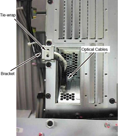
- Remove the bracket of the optical fiber cable, and disconnect
the optical cables from SDCB.note:
There is no need to cut a tie-wrap on the bracket.
Figure 1. Optical Fiber Cable
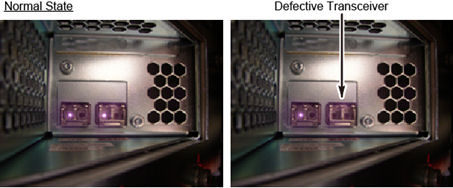
- Visually check the optical output from SDCB Fiber Optic Transceiver
to identify the defective part.
Figure 2. Check Fiber Optic Transceiver
- Turn OFF the 120VAC switch on the gantry’s Service Switch Panel.
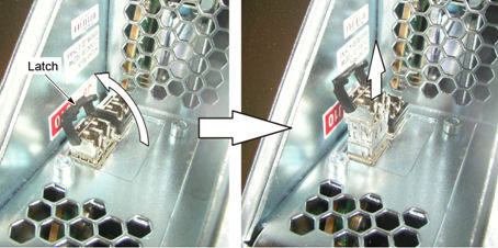
- Remove the defective Fiber Optic Transceiver from the SDCB Board
Assembly.
Figure 3. Fiber Optic Transceiver Removal
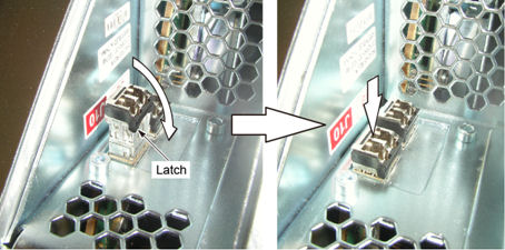
- Install new Fiber Optic Transceiver to the SDCB Board Assembly.
Figure 4. Fiber Optic Transceiver Installation
- Turn ON the 120VAC switch on the gantry’s Service Switch Panel.
- Confirm that the optical output from SDCB Fiber Optic Transceiver is normal.
- Connect the optical cables to SDCB Fiber Optic Transceiver and install the bracket of the optical fiber cable (Torque: 7.9Nm).
 |
3 Gantry Reassembly
Procedure
- Turn ON the Axial Drive and HVDC switches on the gantry’s Service Switch Panel.
- Reinstall gantry right side cover.
4 Finalization
Perform a Scan Data Path test to ensure system operation.