- Topic ID: id_17423481
- Version: 3.0
- Date: Jan 20, 2020 8:34:54 PM
Pump Capacitor Replacement
Prerequisites
Overview
Procedure
- notice
- Raise the Table to its highest position.
- Remove the following covers and component:
-
Cradle (Refer to Cradle)
-
Left and Right Rail Covers (Four(4)x2 Screws)
-
Cradle Tray (Six(6) Screws)
-
- "Remove power from Table by turning off “120VAC”, “Axial Drive” and “HVDC” switches on the service switch panel."
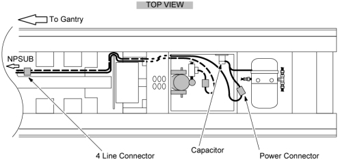
- Remove the capacitor from the capacitor plate by loosing the holding screw (see Figure 1).
- Disconnect the power line connector leading to the pump.
- Disconnect the 4–line connector leading into the NPSUB from the pump capacitor.
- Follow the black and white wires from the four wire connectors
up through the Table U–column to where they meet their upper connector.
This will require cutting the tie wraps leading up through the U–column.
Figure 1. Table Pump / Capacitor Connections
- Install the new capacitor to the capacitor plate and tighten the holding screw.
- Connect the pump power connector.
- Tie up the loose wires with tie wraps.
- Verify that the Table moves up and down normally.
- Restore the Table to original configuration.
 |
Finalization
No finalization steps.