- Topic ID: id_18480236
- Version: 4.0
- Date: Dec 22, 2021 11:23:24 PM
Operator Control Panel Replacement
Prerequisites
Overview
This procedure defines the steps necessary to replace the operator control panels on the gantry covers.
Procedure
- Remove gantry right side cover.
Refer to
- Stop the rotor of X-ray tube in case of Liquid Bearing Tube before HVDC off. Refer to Liquid Bearing Tube Rotor stop procedure for details.
- Turn OFF the Axial Drive, HVDC and 120 VAC switches on the gantry’s Service Switch Panel.
- Remove the gantry left side cover, top covers, scan window and front cover.
- Disconnect the two cables on the top of the control panel.
Figure 1. Gantry control panel
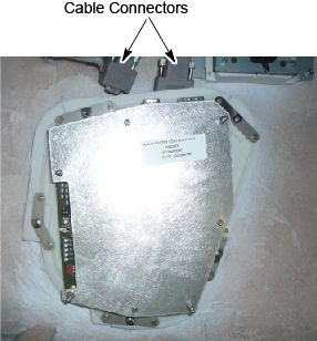
- Loosen five (5) screws that fasten the control panel to the cover.
- Install the new control panel to the cover.
- Reconnect the two cables to the control panel.
- Install the gantry front cover, scan window, top covers, and
left side cover.
Refer to
- Enable 120 VAC HVDC and Axial Drive service switches from the service switch panel. Press the table drives enable button on the lower right corner of the service switch panel.
- Install the gantry right side cover.
Finalization
- Use the controls of the replaced panel to perform the table and gantry movement functions to ensure they work as expected.
- Perform a System Scanning Test from the Functional Checks menu of the service manual to ensure system operation.