- Topic ID: id_17423049
- Version: 3.0
- Date: Apr 22, 2019 12:56:39 AM
Laser Light Replacement
Prerequisites
Overview
This procedure defines the steps necessary to replace and of the gantry laser lights.
Procedure
- Remove gantry right side cover.
Refer to
- Stop the rotor of X-ray tube in case of Liquid Bearing Tube before HVDC off. Refer to Liquid Bearing Tube Rotor stop procedure for details.
- Turn OFF the Axial Drive, HVDC and 120 VAC switches on the gantry’s Service Switch Panel.
- Remove the gantry left side cover, top covers and front cover.
- Disconnect the electrical connection to the defective laser assembly
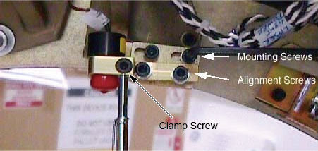
- Loosen laser clamp with a 5 mm hex wrench holding the black
laser in place as shown in Figure 1. If additional clearance is needed, loosen 2
mounting screws (NOT the alignment screws). Remove mounting bracket
if necessary.
Figure 1. Laser Mount Assembly
- Slide the new laser into the mounting bracket and tighten the
clamp screw using a 5 mm hex wrench.
- Torque the Mounting and alignment screws (if touched) to the
following:
Finalization
- Perform Alignment Light Adjustment to check and adjust the new laser.
- Install the gantry front, top and left side covers.
Refer to
- Enable 120 VAC HVDC and Axial Drive service switches from the service switch panel. Press the table drives enable button on the lower right corner of the service switch panel.
- Install the gantry right side cover.
- Perform a System Scanning Test from the Functional Checks menu of the service manual to ensure system operation.