- Topic ID: id_16157505
- Version: 4.0
- Date: Jan 20, 2020 8:34:29 PM
Inverter Mid Power Assembly Replacement
Prerequisites
Overview
To replace the Inverter Mid Power Assembly:
-
If possible, upload JEDI database (from JEDI to console)
-
Remove power unit mounting screws
-
Replace power unit
-
Verify system operation
1 Inverter Mid Power Assembly Removal
Procedure
- Remove the power unit according to Power Unit Replacement.
- Remove the heat sink as follows:
- With the Power Unit standing on end, unscrew seven bolts holding the heat sink.
- Loosen two bolts holding the HV Tank through the heat sink.
- Place the heat sink down on the floor.
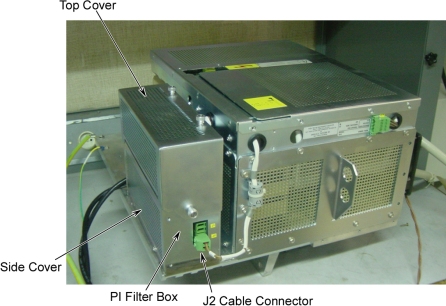
- Remove top and side covers of the PI filter box.
- Disconnect J2 cable connector from PI Filter box.
Figure 1. PI Filter Box
- notice
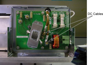
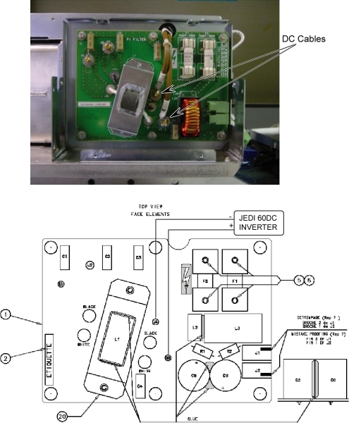
- Using a 10 mm socket wrench, disconnect the two DC cables :–DC,
+DC from the Pi Filter board. And retain the locking washers.
Figure 2. Disconnect DC Cables
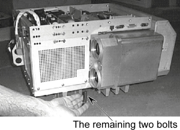
- Remove the remaining two HV Tank retaining bolts from the bottom
of the heat sink.
Figure 3. Bolts of HV Tank
- Separate the Power Unit.

- Remove covers from the Power Unit as follows:
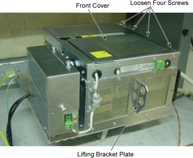
- Unscrew twelve 5.5 mm hex head screws from three sides, and loosen four 5.5 mm hex head screws, then remove the front cover.
- Unscrew and remove the lifting bracket plate.
Figure 4. Front Cover and Lifting Bracket Plate
 note:
note:All the 5.5 mm hex head screws on the Jedi generator are 8 mm long, except for the fourteen screws holding the lifting bracket, which are 12 mm long.
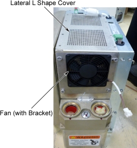
- Unscrew and remove the fan (with bracket), but don’t remove the fan from its bracket.
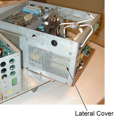
- Unscrew and remove the lateral L shape cover.
Figure 5. Fan and Lateral L Shape Cover
- Remove the Capacitor assembly as follows:
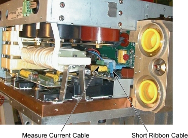
- Disconnect the short ribbon cable from the KV Measure board to the Gate Command board.
- Disconnect the measure current cable from the Capacitor assembly.
Figure 6. Ribbon Cable and Measure Current Cable
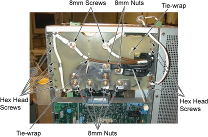
- Cut tie-wraps.
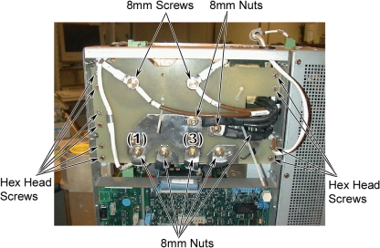
- Unscrew six 8mm nuts and two 8mm screws using 8mm socket wrench.
- Unscrew ten 5.5mm hex head screws.
Figure 7. Capacitor Assembly Removal
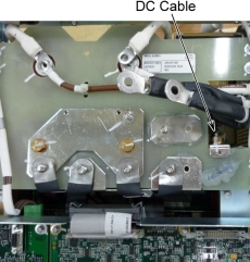
- Unscrew a 8mm nut and remove the DC cable.
Figure 8. Disconnect DC Cable
- Pull and slide the capacitor assembly, and remove it.
Figure 9. Capacitor Assembly Removal
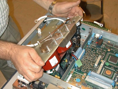
- Remove the Inverter Mid Power Assembly as follows:
- Unscrew the 5.5 mm hex head screws and remove the lateral cover.
(The inverter is now mechanically free).
Figure 10. Lateral Cover Removal
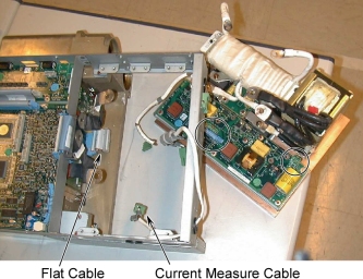
- Disconnect the flat cable and the current measure cable from the gate command board.
- Pull and slide the entire block, and separate the inverter mid
power assembly from the tank and frame.
Figure 11. Flat Cable and Current Measure Cable
- Unscrew the 5.5 mm hex head screws and remove the lateral cover.
(The inverter is now mechanically free).
2 Inverter Mid Power Assembly Installation
Procedure
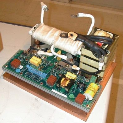
- Put the new inverter power assembly (see the image) in the position
of the old inverter.
Figure 12. Inverter Power Assembly
- Re-install the lateral cover.
Figure 13. Lateral L Cover Installation
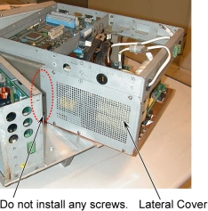 note:
note:Do not place any screws.
- Connect the flat cable to the gate command board.
- Re-install the capacitor assembly as follows:
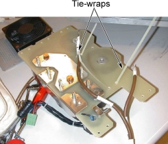
- Add tie-wraps in the position as shown in illustration below.
Figure 14. Tie-wrap on Capacitor Assembly
- Put the Capacitor assembly over the inverter frame but do not insert it.
- Connect the cable of the current measure in the Gate Command board.
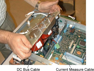
- Insert the Capacitor assembly taking care of the cable of the
DC bus.
Figure 15. Capacitor Assembly Installation
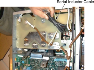
- Put in place and screw the serial inductor cable.
Figure 16. Serial Inductor Cable
- Install and tighten all the 5.5 mm hex head screws to fix the capacitor assembly to the frame.
- Connect all cables of capacitor assembly, and tighten all the
8mm screws and nuts (see Torque
Wrench Information) as shown in illustration
below.
Figure 17. Cable Connection of Capacitor Assembly
- notice
- Close and tight the tie-wraps, and cut the useful extremity of the tie-wraps.
- Add tie-wraps in the position as shown in illustration below.
3 Reassemble the Power Unit
Procedure
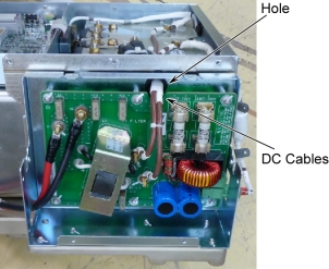
- Position the heat sink while passing the two DC cables through
the hole.
Figure 18. DC Cables
- Re-install the heat sink.
- notice
- Attach + and – wires of the DC cables to the Pi Filter board.
Figure 19. DC Cable Connection
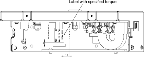
- Insert the screw and grower washer, then tighten to torque 4Nm
on U3 and U4. These torques are written on the label: 4Nm (40kg.cm)
Figure 20. Torque Label
- Put the complete assembly in the vertical position.
- Re-install the following covers and unit, and ensure that proper torque specifications (see Torque Wrench Information) are followed for all fasteners.
- Lift the power unit back on to the gantry and attach it.
- notice
- Reconnect all cables.
- Remount the covers.
|
|
4 Finalization
Procedure
- Run System Scanning Test verify that the system is operational.