- Topic ID: id_15460403
- Version: 4.0
- Date: Jan 20, 2020 8:32:22 PM
IMS Stepping Motor with Pulley Replacement
Prerequisites
Overview
Procedure
- Raise the Table to maximum height.
- Move the Cradle and IMS to OUT limit position.
- Remove power form Table by turning off 120VAC, Axial Drive and HVDC switches on Service Switch Panel.
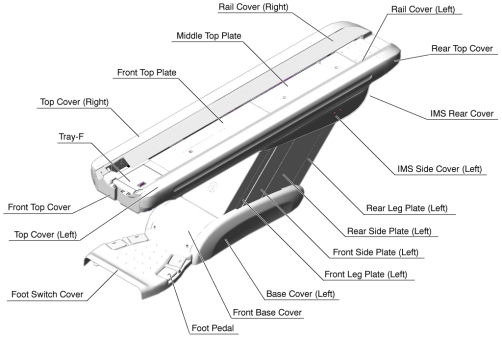
- Remove the following Table covers:
-
Top Cover (Right/Left)
-
Rear Top Cover
-
Rail Cover (Right/Left)
-
All Top Plates
-
IMS Side Cover (Right/Left)
-
IMS Cover Rear
Figure 1. Table Covers
-
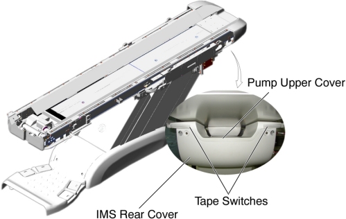
- Disconnect the cable connector of the tape switch.
Figure 2. Tape Switches
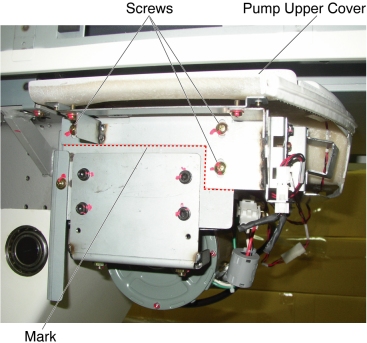
- Remove the pump upper cover as follows:
- To make re-installation easier, mark the position of pump upper cover on both sides by outlining the edge with a maker or pencil.
- Disconnect the cable connectors of the tape switches and touch sensors.
- Remove six (6) screws holding the both sides of the pump upper cover, and remove it.
Figure 3. Pump Upper Cover Removal
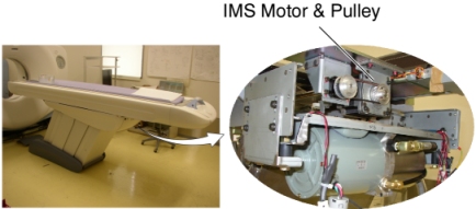
- Remove IMS motor cover.
- Cut any tie-wraps holding the motor wires to the Table frame.
Figure 4. IMS Motor Location
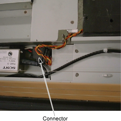
- Disconnect the motor wires connector.
Figure 5. IMS Motor Wires Connector
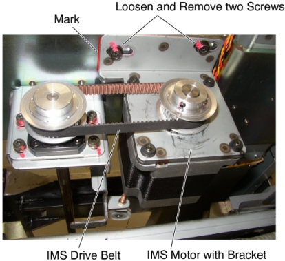
- Mark the motor bracket position for re-installation.
- If the clean damper is mounted on the IMS motor shaft, remove it.
- Loosen 2 screws to remove tension from the belt, and remove the belt from the pulley on the motor.
- Unscrew the 2 screws, and remove the motor with bracket.
Figure 6. IMS Motor Removal
- Install the new motor in place, and position the belt on and around the motor pulley.
- Tighten the 2 screws, to fasten the motor, with tension on the belt.
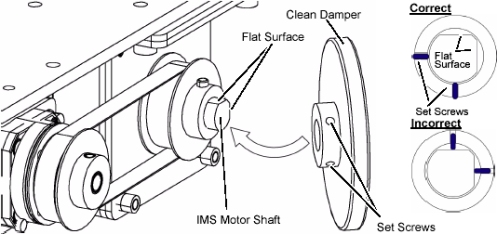
- If the clean damper is removed, re-install it to the IMS motor
shaft.
Figure 7. Clean Damper Installation
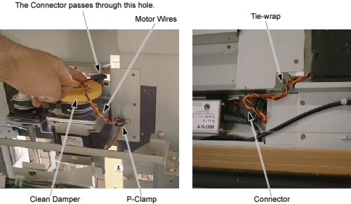
- Perform the following appropriate step (a or b) :
-
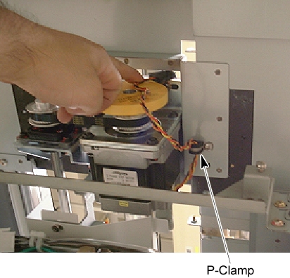
(For Table with P-Clamp at the bottom of the Table support
frame Or the P-Clamp is included in the replacement kit)
Figure 8. P-Clamp
-
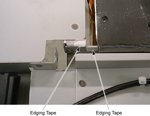
Attach the edging tape included in the replacement kit to the Table bracket.
Figure 9. Edging Tape
-
Route the motor wires through the p-clamp as shown in illustration below, and re-connect the motor wires connector, then fasten the wires to the Table bracket with tie-wraps.
note:Verify that the motor wires do not interfere with the clean damper.
Figure 10. IMS Motor Wires Routing
-
-
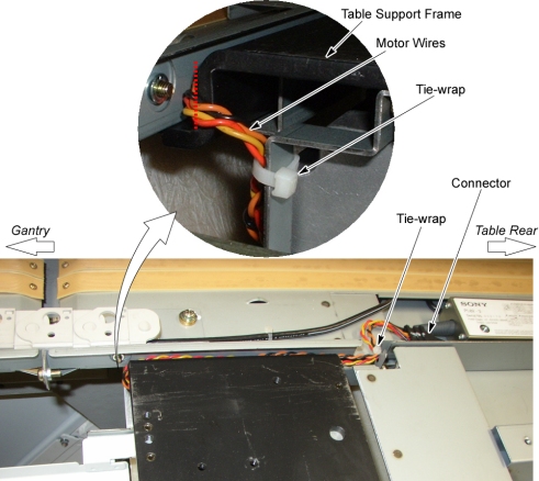
(For Table without P-Clamp at the bottom of the Table
support frame And the P-Clamp is not included in the replacement kit)
-
Route the motor wires from the side edge of the Table support frame (red dotted line) as shown in illustration below, and re-connect the motor wires connector, then fasten the wires to the Table frame with tie-wraps.
Figure 11. IMS Motor Cable Wiring
-
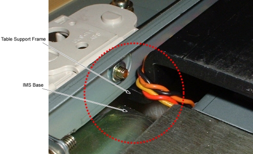
Move the IMS to mechanical IN limit position by hand, and verify that the motor wires are not caught between the IMS base and the Table support frame.
Figure 12. Check IMS Motor Wires
-
-
(For Table with P-Clamp at the bottom of the Table support
frame Or the P-Clamp is included in the replacement kit)
Finalization
- Power up the Table from the Service Switch Panel.
- Using the service switches on GTCB, move the IMS in and out.
When the Table functions properly, turn off all 3 switches (Axial Drive, HVDC, 120VAC), and reinstall the Table covers.
- Power up the Table from the Service Switch Panel, and move the cradle and IMS IN and OUT completely 10 cycles, and verify that the Table movement is operating normally.