- Topic ID: id_15460386
- Version: 3.0
- Date: Apr 22, 2019 12:55:51 AM
IMS Characterization Procedures
Prerequisites
Overview
Procedure
- Move the table to the UP-limit position.
- Remove the top right cover, right IMS cover, and front base cover.
- Set the service switch (MODE_SEL) to the SERVICE to enter the service mode.
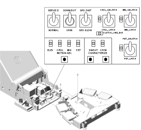
- Confirm that the “IM” LED on the GTCB board in the
table is ON. If it is NOT ON, press the “Motion Target”
button until “IM” LED is ON.
Figure 1. LED's on GTCB board
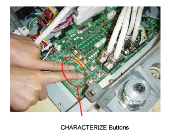
- Press the two “Characterize” Buttons at the same
time to start characterization.
Figure 2. Starting Characterization
- Confirm that the “UP/IN” LED is ON. See Figure 1.
- Using the Service Switches (ACTION), move the IMS until it is set outside of the characterization points on the IMS frame rail.
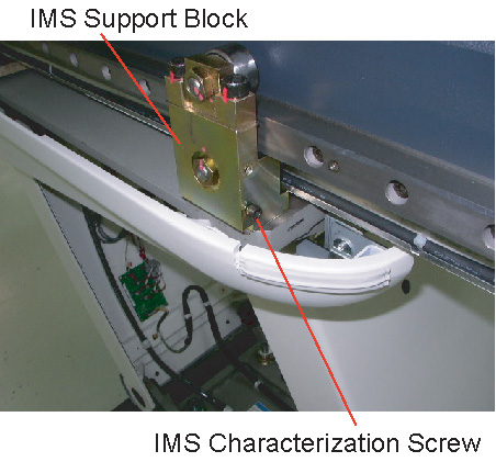
- Remove the IMS characterization screw from the IMS support block.
Figure 3. IMS Characterization screw
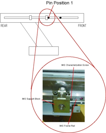
- Insert the IMS characterization screw into the frame rail (Position
1) as shown, then move the table until the screw touches the IMS support
block.
Figure 4. Inserting the Characterization Screw (Position 1)
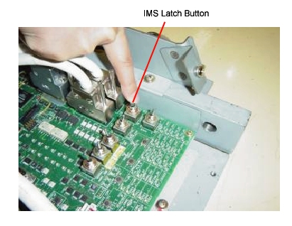
- Set the IMS latch button to “IM_UNLATCH” position
to unlatch the IMS.
Figure 5. Set to IMS_UNLATCH
- Move the IMS backward manually until the IMS characterization screw touches the IMS support block.
- Press the two “Characterize” Buttons at the same time. See Figure 2.
- Confirm that the “DOWN/OUT” LED is ON. See Figure 1.
- Remove the IMS characterization screw from the rail.
- Set the IMS latch button to “IM_LATCH” position to latch the IMS. See Figure 5.
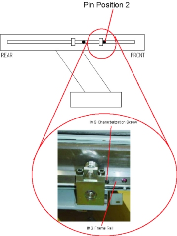
- Using the Service Switches, move the IMS until it is set to the characterization points (Position 2) on the IMS frame rail.
- Insert the IMS characterization screw into the frame rail, then
move the table until the screw touches the IMS support block.
Figure 6. IMS Characterization Screw (Position 2)
- Set the IMS latch button to “IM_UNLATCH” position to unlatch the IMS. See Figure 5.
- Move the IMS backward manually until the IMS characterization screw touches the IMS support block.
- Press the two “Characterize” Buttons at the same time. See Figure 2.
- Confirm that both of “DOWN/OUT” LED and “UP/IN” LED are ON. See Figure 1.
- Remove the IMS characterization screw from the rail.
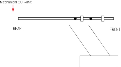
- Move the IMS backward manually to the mechanical OUT-limit position.
Figure 7. Mechanical OUT limit position
- Press the two “Characterize” Buttons at the same time. See Figure 2.
- 5 - 10 seconds later (to write characterization data to the flash memory), confirm that both of LED's (UP/IN and DOWN/OUT) are OFF.
- Set the IMS latch button to “IM_LATCH” position to latch the IMS. See Figure 1.
- If both of LED's blink during procedures, it means that characterization fails. Retry characterization.
- Re-install the IMS characterization screw to the proper position (the lower side of the IMS support block). See Figure 3
- When finished with characterization set the service switch (MODE_SEL) to the NORMAL position for customer use.
Finalization
- Install the covers in the reverse order of removal.