- Topic ID: id_15460400
- Version: 4.0
- Date: Jan 20, 2020 8:31:50 PM
IMS Cable Bear Assy Replacement
Prerequisites
Overview
Procedure
- Raise the Table to maximum height.
- Move the Cradle and IMS to OUT limit position.
- Remove power from Table by turning off 120VAC, Axial Drive and HVDC switches on Service Switch Panel.
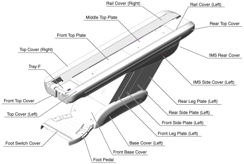
- Remove the following Table Covers:
-
Top Cover (Right/Left)
-
Front Top Cover
-
Rail Cover (Right/Left)
-
Rear Top Plate
-
IMS Rear Cover
-
IMS Side Cover (Right/Left)
-
Liner Scale Cover
Figure 1. Table Covers
-
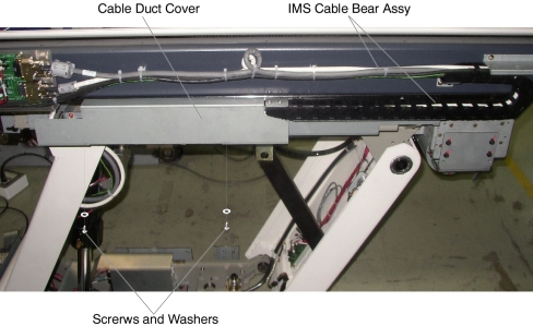
- Remove two screws holding the cable duct cover, and remove the
cable duct cover from the Table.
Figure 2. Cable Duct Cover Removal
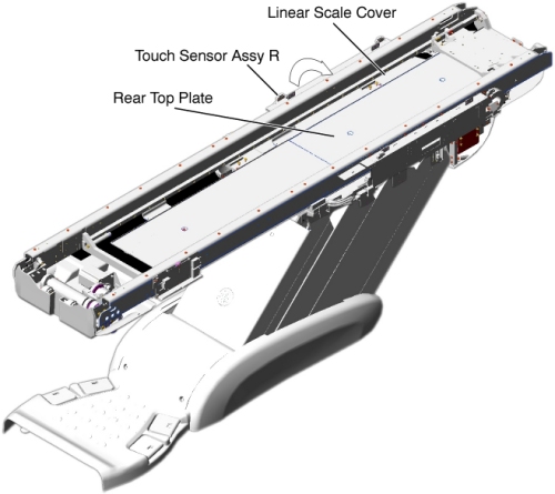
- Remove the Touch Sensor Assy R (it is necessary to disconnect
the cable connector), and put it on the Table frame.
Figure 3. Preparation for IMS Cable Bear Assy Replacement
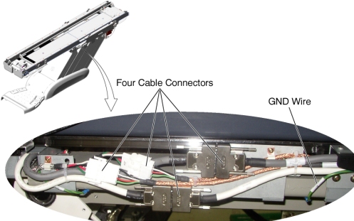
- Disconnect four cable connectors and a GND wire on the cable
duct, and remove any clamps.
Figure 4. Cable Connection of Cable Duct
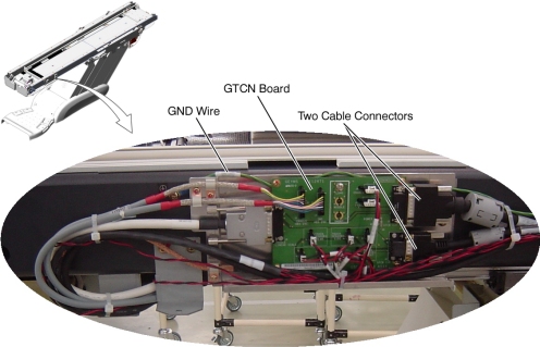
- Disconnect two cable connectors and a GND wire from the GTCN
board, and remove any clamps.
Figure 5. Cable Connection of GTCN
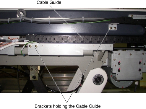
- Remove two support brackets (holding the IMS cable guide to
the IMS frame) by unscrewing 2 (x2) screws.
Figure 6. Support Bracket Removal
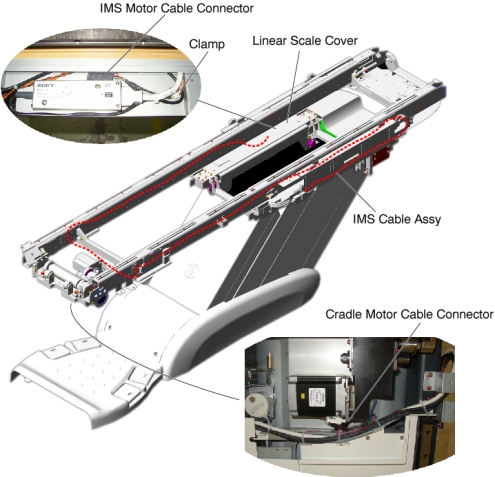
- Cut any tie-wraps holding the IMS cable to the Table frame,
and remove any clamps, then disconnect the following cable connectors:
-
Cradle Motor Cable Connector
-
IMS Motor Cable Connector
Figure 7. IMS Cable Assy Routing
-
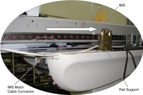
- Move the IMS so that the cable outlet is behind the rail support.note:
Cable Outlet Cable Outlet There is not enough space between the rail support and the IMS frame for the cable connector to pass through. By moving the cable outlet of the IMS to behind the rail support, the cable connector can be removed through this space.
Figure 8. Cable Outlet of IMS Frame
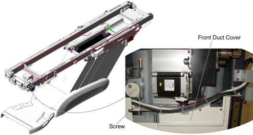
- Remove a screw holding the front duct cover to the under Table
frame and remove the IMS cable bear assembly from the Table.
Figure 9. Front Duct Cover
- Install the new IMS Cable Bear Assy by referring to Step 12through Step 7.
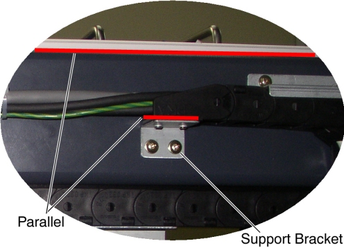
- Verify that the top surface of the support bracket is parallel
with the top surface of the Table frame.
Figure 10. Support Bracket Configuration
- Verify that the cable connector of the IMS motor does not interfere with IMS/Cradle movement.
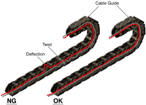
- Verify that the cables in the cable guide have no deflection
and are not twisted.
Figure 11. Cable Configuration in the cable guide
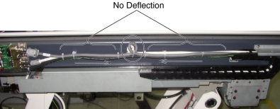
- Verify that the cables on the Table frame have no deflection.
Figure 12. Cable Configuration on the Table Frame
Finalization
- Re-install the touch sensor assy R, all removed Table trays and covers.
- Power up the Table from the Service Switch Panel.
- Verify that the IMS moves IN and OUT normally.