- Topic ID: id_15460385
- Version: 4.0
- Date: Jan 20, 2020 8:31:55 PM
IMS Bearing Tension Adjustment
Prerequisites
Overview
Procedure
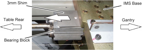
- Disengage the bearing blocks from the IMS base by unscrewing 2 screws, refer to IMS Bearing Block Replacement.
- Move the IMS bearing away from the Gantry by rotating the IMS
shaft.
Figure 1. Bearing Block Disengagement
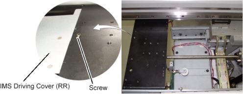
- Remove a screw holding the IMS driving cover (RR) to the Table.
Figure 2. Screw Removal
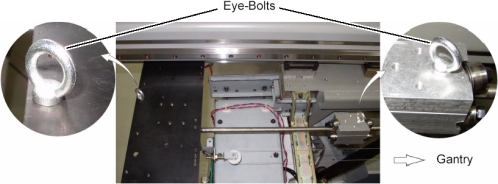
- Set eye-bolts to Table frame and the bearing block.
Figure 3. Support Screw Setting
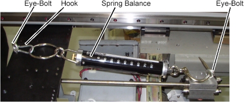
- Set the spring balance to the eye-bolts.
Figure 4. Spring Balance Attachment
- Make sure of the bearing block tension as follows:
 caution
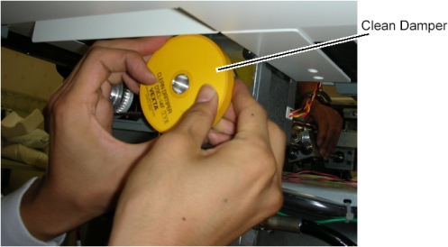
- Hold and rotate the clean_damper by hand.
- Keep the IMS shaft rotating in manner of above step to move
the bearing block in the IN direction.The bearing block movement will automatically stop at some position of the IMS shaft depending on how much of the bearing tension, read the peak value of the spring balance at this position.
Figure 5. Clean Damper Rotating
 note:
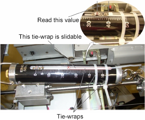
note:One way of reading the peak value of the spring balance.
-
Attach 2 tie-wraps as shown in illustration below.
-
Read the peak value of the spring balance.
Figure 6. Bearing Tension Measurement (by way of example only)
-
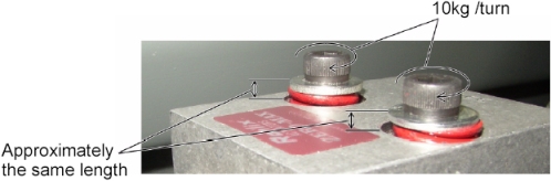
- Verify that this value is 52 kg ± 2 kg.If the value is out of specification, adjust the bearing tension by turning two set screws on the bearing block evenly (10kg/turn).
Figure 7. Two Set Screws of Bearing Block

- Remove two eye-bolts from the bearing block and the Table frame.
- Engage the bearing block to the IMS base, refer to IMS Bearing Block Replacement.
Finalization
- Power up the Table from the service Switch Panel.
- Move the cradle and IMS in and out completely 10 cycles and verify that table movement is operating normally.
- Turn off all 3 switches (Axial Drive, HVDC, 120VAC), and re-install the Table covers.