- Topic ID: id_17423024
- Version: 3.0
- Date: Apr 22, 2019 12:56:11 AM
Home Flag Sensor Board Assembly Replacement
Prerequisites
Overview
This procedure defines the necessary steps to replace the home flag sensor board or assembly.
1 Preparation
Procedure
- Move the table to the home position.
- Remove gantry right side cover.
Refer to
- Stop the rotor of X-ray tube in case of Liquid Bearing Tube before HVDC off. Refer to Liquid Bearing Tube Rotor stop procedure for details.
- Turn OFF the Axial Drive and HVDC switches on the gantry’s Service Switch Panel.
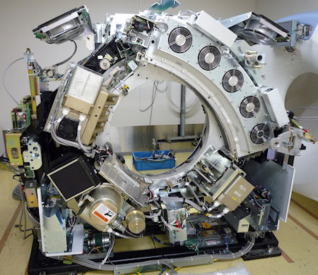
- Rotate the gantry to place the tube at about the 7o'clock position
for easier access to the sensor board.
Figure 1. Tube Position
- Turn OFF the 120 VAC switch on the gantry’s Service Switch Panel.
- Remove the gantry left side cover, top covers and front cover.
2 Replace Sensor Board or Sensor board assembly
Procedure
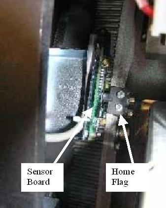
- Locate the Home Flag Sensor board (Figure 2) near the encoder
assembly (Gantry 11 o'clock location).
Figure 2. Home Flag and Sensor Board
- Disconnect the harness from the sensor board.
- If replacing the Sensor board assembly (with bracket) follow
this step.
Using a 5 mm hex wrench remove the M6 screws attaching the bracket assembly to the frame. See Figure 3.
Figure 3. Home Flag Sensor Assembly
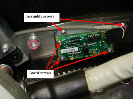
- If replacing the Sensor board only, follow this step.
Using a 3 mm hex wrench remove the M4 screws attaching the sensor board to the bracket assembly. See Figure 3 for board screws.
- Replace Sensor board or Board Assembly installing the screws previously removed, tightening 1/4 turn past seated.
- Reconnect cable to the sensor board.
3 Restore Gantry
Procedure
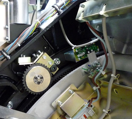
- Slowly rotate gantry by hand and adjust flag position to pass through the center of the opto-sensor on the sensor board. The home flag is next to the 48V Power supply.
- Make sure that the flag is centered in the opto-sensor on the
sensor board (Figure 4) and does not make contact with it. Looking
at the side view along the side of the 48V PS as shown in Figure 5 can help.
Figure 4. Flag Position Top View
Figure 5. Flag Position Side View
- If necessary, adjust by loosening the screws and slightly shifting the board. (reposition gantry for easy access along side of the tube as done previously)
- Perform the Reset the C-Pulse procedure.
- Install the gantry front cover, top covers and left side cover.
Refer to
- Enable 120 VAC HVDC and Axial Drive service switches from the service switch panel. Press the table drives enable button on the lower right corner of the service switch panel.
- Install the gantry right side cover.
4 Finalization
Procedure
- Perform a System Scanning Test from the Functional Checks menu of the service manual to ensure system operation.