- Topic ID: id_15460457
- Version: 8.0
- Date: Dec 28, 2021 10:03:21 PM
HOT ISO Alignment
Prerequisites
Overview
This procedure provides steps for HOT ISO Alignment.
Procedure
- Select the CALIBRATION tab in the Common Service Desktop.
- Select HOT ISO ALIGNMENT.
- Remove any objects from the detector FOV. (Cradle, phantoms, Mylar window, etc.)
- Click the first Scan button to execute the Tube Warmup scan. (“Tube Warmup” is displayed as “Heat Soak and Seasoning” in previous software version.)
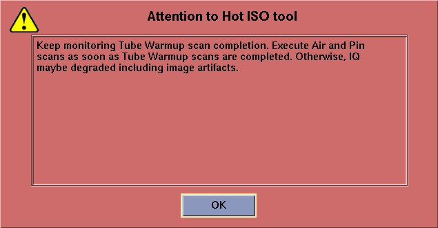
- If the attention popup message appears as shown in Figure 2, CAREFULLY READ and Click OK.
Figure 1. HOT ISO Screen
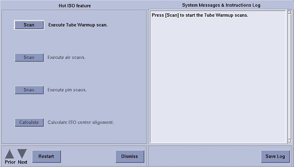
Figure 2. Attention Window
- Press START on the SCIM/GSCB when it flashes.
- Click the second Scan button to execute the Air Scans (small spot and large spot).
- Press START on the SCIM/GSCB when it flashes.
- Place an 1/8 in. screwdriver on the phantom holder (should be pointing into the Z direction). Turn ON the laser alignment lights. Advance the adjust the table to position the metal shaft 35 mm up and 35 mm to the right of ISO center as marked by the laser alignment lights. Make sure the shaft remains perpendicular to the scan plane.
- Click the third Scan button to execute Pin Scans (small spot and large spot).
- Press START on the SCIM/GSCB when it flashes.
- Click the Calculate button to calculate correction factor. note: No movement of the tube is required. This is a software correction done automatically.note:
(FOR Liquid Bearing Tube) Tube warmup scan can be completed approximately 5 minutes at the shortest depending on Tube temperature. Execute Air and Pin scans as soon as tube warmup completed. Otherwise IQ maybe degraded including image artifacts.
(FOR Ball Bearing Tube) Tube warmup scan can be completed approximately 25 minutes. Execute Air and Pin scans as soon as tube warmup completed. Ohterwise IQ maybe degraded including image artifacts.
Finalization
No finalization steps.