- Topic ID: id_16157502
- Version: 4.0
- Date: Jan 20, 2020 8:36:04 PM
Gantry Top Covers Removal and Re-Install
Prerequisites
Overview
This procedure explains how to remove and re-install the CT Gantry top covers.
1 Top Cover Removal
Procedure
 caution
- Remove the gantry right side cover.
- Stop the rotor of X-ray tube in case of Liquid Bearing Tube before HVDC off. Refer to Liquid Bearing Tube Rotor stop procedure for details.
- notice
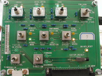
- Turn OFF the three (3) main power switches (HVDC, 120VAC, and Axial Drive) on the Service Switch Panel (SSP). See Figure 1.
Figure 1. Service Switch Panel
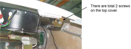
- Unscrew two screws that secure the top cover with Philip top
screwdriver. See Figure 2.
Figure 2. Screws Securing Top Cover
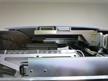
- Take the end of the top cover nearest to the side cover and tilt upwards.
- Slide the cover down to disengage the tab from the mounting bracket.
Figure 3. Top Cover Tabs and Bracket
- Lift the cover clear and repeat the above steps for the other cover.
 |
2 Top Cover Installation
The top cover consists of two (2) pieces. Install the front and rear gantry covers, if not already installed.
Procedure
- Take one of the top covers and align the tabs on the cover with its associated bracket. Lift and slide the cover into place. Secure 2 screws on the top cover.
- Take the other top cover and align the tabs on the cover with its associated bracket. Lift and slide the cover into place. Secure 2 screws on the top cover.
- notice
- Turn on the three (3) power switches.
- Ensure fans work properly.
- Re-install the gantry side covers.
|
3 Finalization
Procedure
- Verify all covers, especially side covers are properly secured.
- Ensure there is no interference during all tile range.