- Topic ID: id_16157525
- Version: 4.0
- Date: Jan 20, 2020 8:32:15 PM
Gantry Rear Cover Removal and Re-Install
Prerequisites
Overview
This procedure explains how to remove and re-install the CT Gantry rear cover.
1 Sliding Out Rear Cover
Procedure
 danger
- Stop the rotor of X-ray tube in case of Liquid Bearing Tube before HVDC off. Refer to Liquid Bearing Tube Rotor stop procedure for details.
- notice
- notice
- Remove Gantry side covers, top covers and Mylar window.
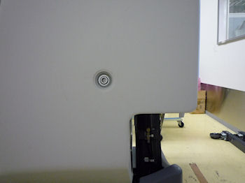
- Use a 10mm Hex wrench to unlatch the rear cover.
Figure 1. Rear Cover Unlatch
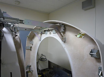
- Slide out the rear cover by pulling the cover backward.
Figure 2. Rear Cover
 |
|
2 Rear Cover Removal
Procedure
- caution
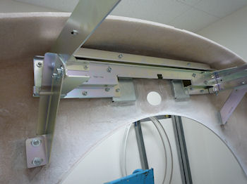
- Install the rear cover dolly.
- Tighten the two (2) shoulder bolts to the rear cover. Use the extending bolt for the upper side.
- Fit side dolly through the shoulder bolts and secure assembly with two (2) wing nuts.
- Repeat steps a and b for the other side dolly.
- Remove rear cover by removing 8 screws, which attach the rear
cover to the brackets.
Figure 3. 8 Screws of Rear Cover
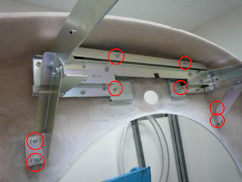
Figure 4. Removed Rear Cover
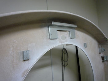
- Move cover away from gantry as needed.
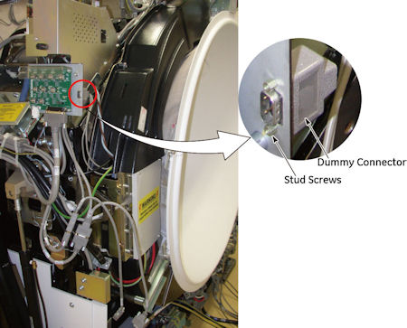
If the rear switch panel option was installed, connect the cable to terminator.
Figure 5. Dummy Connector
 |
3 Installation
Procedure
- Position cover in back of gantry.
- Attach the rear cover to the brackets by 8 screws.
Figure 6. Rear Cover Attachment
- Return the terminate cable to original.
- Remove cover dolly, disassemble and store safely away.
- Push the rear cover to gantry frame and secure the cover by turning two (2) latches.
4 Finalization
Procedure
- Continue with other cover installation procedures as necessary. When AC power is restored to the system, prior to enabling axial drive or HVDC, remember to rotate the gantry by hand to ensure there is no interference between covers and rotating components.
- Verify all covers, especially side covers are properly secured.
- Ensure there is no interference during all tilt angle.