- Topic ID: id_16157524
- Version: 4.0
- Date: Jan 20, 2020 8:34:31 PM
Gantry Front Cover Removal and Re-Install
Prerequisites
Overview
This procedure explains how to remove and re-install the CT Gantry front cover.
1 Redesigned Front Cover Dolly Setup
Procedure
 danger
- notice
- notice
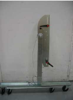
- Bring Dolly out of storage into open space (see Figure 1).
Figure 1. Front Cover Dolly in Storage Mode
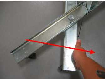
- Pull feet out to form cross (see Figure 2).
Figure 2. Front Cover Dolly Base Assembly
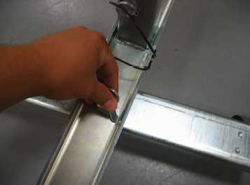
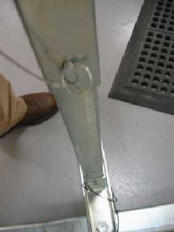
- Place the pin to secure the feet into position (see Figure 3).
Figure 3. Place Pin to Secure Feet
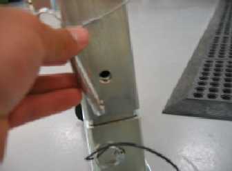
- Remove the pin from the cover bracket tube (see Figure 4).
Figure 4. Remove Pin from Tube
- warning
- Raise the bracket to the proper height and secure it by inserting
the pin into the upper hole on the support tube (see Figure 5).
Figure 5. Secure Bracket with Pin
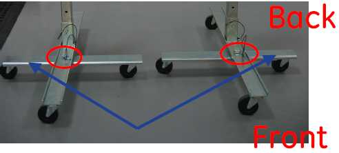
- Position dolly so the pivot bolt for the feet is on the table
side (front side) of the gantry (see Figure 6).
Figure 6. Dolly Feet Configuration
 note:
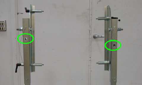
note:The short part of the feet faces outwards toward the wall. The L and R stickers (If existing) (see Figure 7) refer to the sides as you face the gantry from the front.
Figure 7. Direction Stickers
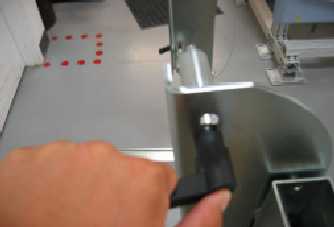
- Once the studs are secured on the cover, tighten the ratcheting
handle (see Figure 8).The handle can be pulled out and turned to clear the support tube.
Figure 8. Ratcheting Handle Button
- Turn the handle to HAND TIGHT.
 |
|
 |
2 Removal
Procedure
- Position the table at its lowest position.
- Stop the rotor of X-ray tube in case of Liquid Bearing Tube before HVDC off. Refer to Liquid Bearing Tube Rotor stop procedure for details.
- notice
- Remove gantry side and top covers, if you have not already done so.
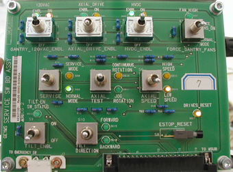
- Verify the three (3) power switches have been turned OFFFigure 9.
Figure 9. Service Switch Panel
- Assemble the front cover dolly.
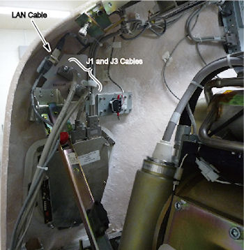
- Detach front cover J1 and J3 and LAN cables.
Figure 11. Front Cover Cables
- Remove the Mylar (scan) window.
- Remove front cover.
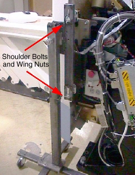
- Disengage upper cantrell bracket on right side of the cover.
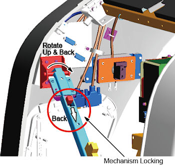
Figure 12. Releasing Cover Brackets
-
Disengage the locking mechanism on the upper cantrell brackets by using your thumb to slide the trigger (red lever) back. This will release the locking mechanism and allow the cantrell to be rotated upwards with steady and firm pressure.
-
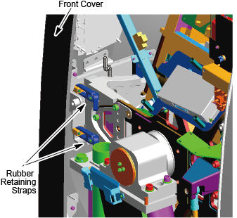
Disengage the rubber retaining straps on right side. See Figure 13. You may find it helpful to lift “up” on the cover to align the stud while attaching the rubber retaining straps.
Figure 13. Rubber Retaining Straps and Cover Locking Mechanism
-
- Disengage the left side of the front cover
-
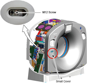
Remove the small cover from the front cover.
-
Loosen M12 screw.
Figure 14. Disengage the Left Side of the Front Cover
-
- Lift and rotate cover locking arm to unlocked position.
- Disengage upper cantrell bracket on right side of the cover.
- Rotate front cover away from gantry.
- Move front cover away from gantry, leaving space (about 5 feet) between cover and gantry.
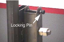
- Pull the locking pin and rotate front cover away from gantry.
Place locking pin in one of the side dolly perforations. See Figure 15.
Figure 15. Releasing Front Cover Dolly Hinge
- Continue cover removal per Figure 16.
Figure 16. Front Cover Removal Sequence
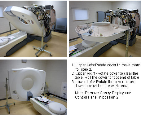
- Rotate the cover horizontally and move it back and over the table to a safe location. Once in a safe location, you may over-rotate the cover full vertically but upside down.
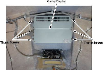
- Remove the gantry display from the front cover and place it
into its service position if scan is required during maintenance.
- The gantry display is held in place with (6) thumb screws. Use
a flat-blade screwdriver to remove the Display. See Figure 17.
Figure 17. Gantry Display Removal
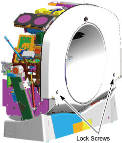
- Loosen two lock screws of the rear cover.
Figure 18. Lock Screws of the Rear Cover
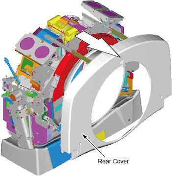
- Side the rear cover backward.
Figure 19. Rear Cover Slide
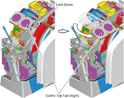
- Loosen the lock screw of the right top fan of the gantry, and
rotate the right top fan.
Figure 20. Top Fan Rotation
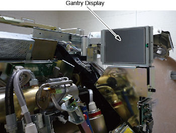
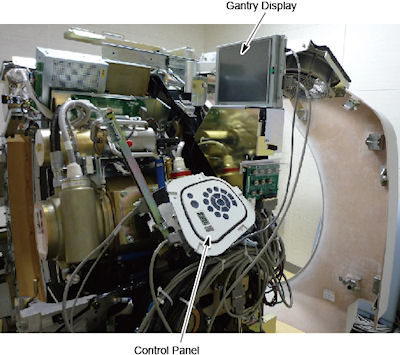
- Place the Display in the bracket on the right side of the gantry. See Figure 21.
Figure 21. Gantry Display Service Mounting Location
- Connect the LAN cable to the Gantry Display.
- The gantry display is held in place with (6) thumb screws. Use
a flat-blade screwdriver to remove the Display. See Figure 17.
- Remove right gantry control assemblies, and place it into its
service position.
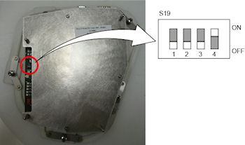
- Loose five (5) screws that fasten the control panel to the cover. See Figure 22. Keep one hand on the control panel at all times to prevent it from dropping to the floor.
- Set dip switch s19-4 to ON position.
Figure 22. Dip Switch S19 - 4 Setting
- Align the ball studs with their associated receivers and snap into place.
Figure 23. Control Panel Service Position
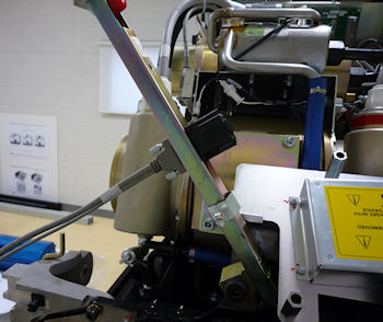
- Connect FCVR BKHD J1 cable to terminator located on the cantrell
arm. See Figure 24.
Figure 24. Gantry Service Mode Cable Terminator
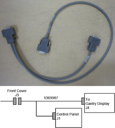
- Connect the FRT CVR J3 cable to the extension cable 5369987
and connect the other end of the connectors to display and control
panel.
Figure 25. FRT CVR J3 Cable
|
3 Installation
Procedure
- Remove the gantry display and control assembly from their service
positions and reattach them to the gantry cover.
- Disconnect cables from Display and Gantry Control Panels.
- Install Gantry Display in front cover. Secure the 6 thumbscrews. With a flat-blade screwdriver, gently tighten past finger-tight.
- Set the dip switch on the control panel to original position.
- Install the gantry control panel, Secure the 5 screws.
- Reattach cables.
- notice
- Rotate gantry front cover back to its vertical position.
- Attach the front cover.
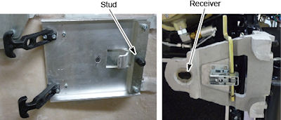
- Align the studs on both sides of the front cover with each associated
receiver. Receiver is located on the gantry frame.
Figure 26. Cover Stud and Mounting Bracket Receiver
- For Right Side:
Insert the stud on one side into its associated receiver and attach the rubber retaining straps.Then insert the stud on the other side into its associated receiver and attach its rubber retaining straps.
You may find it helpful to lift "up" on the cover to align the stud while attaching the rubber retaining straps.
- Reattach upper cantrell brackets on right side.
- For Left Side:
Insert the stud onto it's associated receiver and fasten the M12 screw and install the small cover (see Figure 14).
- Align the studs on both sides of the front cover with each associated
receiver. Receiver is located on the gantry frame.
- Remove dolly, disassemble and store safely away for later use.
- Reattach cables to cover.
- Re-install the Mylar (scan) window.
|
4 Finalization
Procedure
- Continue with other cover installation procedures as necessary. When AC power is restored to the system, prior to enabling axial drive or HVDC, remember to rotate the gantry by hand to ensure there is no interference between covers and rotating components.
- Verify all covers, especially side covers are properly secured.
- Ensure there is no interference during all tilt range.