- Topic ID: id_16157498
- Version: 4.0
- Date: Jan 23, 2022 10:51:46 PM
Gantry Cover Tilt Sensor Replacement
Prerequisites
Overview
This procedure defines the steps necessary to replace the Gantry front and rear cover tilt sensor replacement.
1 Preparation
Procedure
- Move Table to the home position.
- Remove gantry right side cover.
Refer to
- Stop the rotor of X-ray tube in case of Liquid Bearing Tube before HVDC off. Refer to Liquid Bearing Tube Rotor stop procedure for details.
- Turn OFF the Axial Drive, HVDC and 120 VAC switches on the gantry’s Service Switch Panel.
- Remove the gantry left side cover, top covers and front cover.
2 Front Cover tilt sensor
Procedure
- On the back of the front cover disconnect touch strip cable
from the tilt sensor.
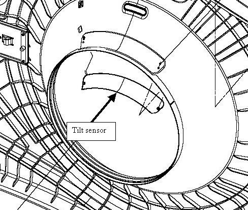
Figure 1. Gantry Tilt Sensor on Front Cover
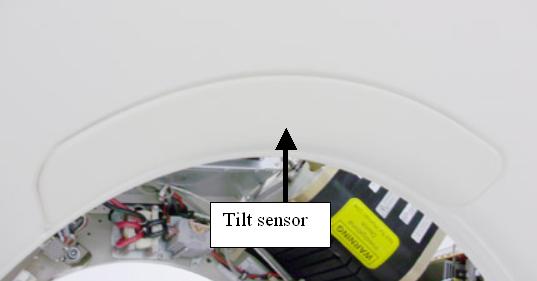
Figure 2. Front cover Tilt Sensor
- Remove 2 nuts (7 mm socket) that secure touch sensor pad to the front cover.
- Install new touch pad and tighten the 2 nuts to the following
values.
3 Rear Cover tilt sensor
Procedure
- Remove the bore cover.
Refer to
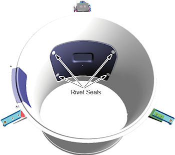
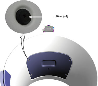
- Remove four (4) rivet seals from tilt sensor.
Figure 3. Rivet Seals
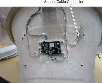
- Pull out the cable with connector underneath the hole in the bore, and then disconnect the connector.
Figure 4. Tilt Sensor Cable Connector
- Turn the rivets, and remove the tilt sensor from the bore cover.
Figure 5. Rivets
- Install the new tilt touch sensor.
- Reconnect the sensor cable connector.
- Attach rivets seals on the four rivets.
- Restore the gantry covers.
4 Gantry reassembly
Procedure
- Enable 120 VAC HVDC and Axial Drive service switches from the service switch panel. Press the table drives enable button on the lower right corner of the service switch panel.
- Install the gantry right side cover.
5 Finalization
Procedure
- From the front cover control panel, press and hold the gantry forward tilt button and then press on the tilt sensor while still tilting gantry. Verify the gantry tilt stops.