- Topic ID: id_16157880
- Version: 4.0
- Date: Jan 20, 2020 8:35:18 PM
Foot Switch Assembly Replacement
Prerequisites
Overview
Procedure
- Raise the Table to maximum height.
- Move the Cradle and IMS to OUT limit position.
- Remove power from Table by turning off 120VAC, Axial Drive and HVDC switches on Service Switch Panel.
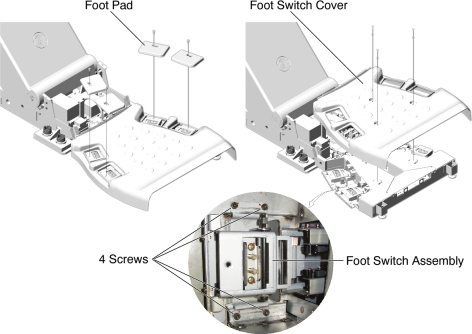
- Remove 4 foot pads from the foot switch assembly.
- Remove a foot switch cover by unscrewing 3 screws.
- Unscrew 4 screws holding the Foot Switch Assembly, and disconnect
the cable connector, then remove the Foot Switch Assembly from the
foot switch base assembly.
Figure 1. Foot Switch Assembly Removal
- Install the new Foot Switch Assembly by referring to Step 6 through Step 4.
Finalization
- Power up the Table from the Service Switch Panel.
- Verify that the foot switch function is operating normally.
- Turn off all 3 switches (Axial Drive, HVDC, 120VAC), and re-install the foot switch cover and the 4 foot pads.