- Topic ID: id_15460396
- Version: 5.0
- Date: Dec 31, 2020 12:35:18 AM
Elevation Potentiometer Replacement
Prerequisites
Overview
Procedure
- Set GTCB to Service mode and raise the Table to upper mechanical limit. Then set GTCB to Normal mode.
- Move the Cradle and IMS to OUT limit position.
- Remove power from Table by turning off 120VAC, Axial Drive and HVDC switches on Service Switch Panel.
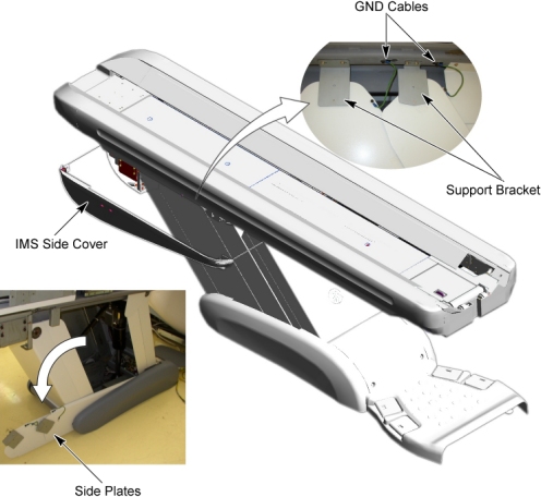
- Remove IMS side cover (right).
- Disconnect 2 GND cables from the Table frame.
- Remove 2 upper support brackets of the side plates (right) by
unscrewing its 2 (x2) screws, and open the side plates.
Figure 1. Table Covers Removal
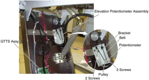
- Cut any tie-wraps holding the potentiometer cable to the Table frame.
- Disconnect the potentiometer cable connector from the GTTS assy.
Figure 2. Elevation Potentiometer Removal
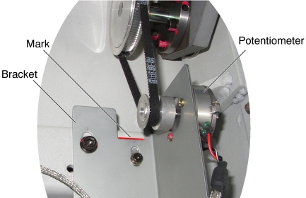
- Mark the bracket position for re-installation.
- Loosen 2 screws that fasten the Potentiometer assy to the Table frame, to remove the tension from the potentiometer belt, and remove the belt from the potentiometer pulley.
- Unscrew the 2 screws, and remove the potentiometer assy from
the Table.
Figure 3. Elevation Potentiometer
- Unscrew 3 screws holding the potentiometer to the bracket, and remove the potentiometer from the bracket.
- Attach the new potentiometer to the bracket using the 3 screws.
- Position the new potentiometer with bracket on the Table frame.
- Re-connect the potentiometer cable connector, and fasten the cable to the Table frame with tie-wraps.
- Power up the Table from the Service Switch Panel.
- Rotate the potentiometer pulley until a LED (POT_ADJ UP) on the GTCB Assy is ON.
- Position the belt on and around the pulley with the LED on.
- Align the surface of the bracket with the mark, and tighten the 2 screws, to fasten the potentiometer assy , with tension on the belt.
Finalization
- Perform Elevation Characterization.
- Raise and lower the Table a couple times and verify that Table movement is operating normally.
- Turn off all 3 switches (Axial Drive, HVDC, 120VAC), and re-install the Table Covers.