- Topic ID: id_17423029
- Version: 4.0
- Date: Jan 20, 2020 8:31:48 PM
Detector Collimator Unit Replacement - Merc40
Prerequisites
Overview
This procedure defines the necessary steps to Remove and Install the Detector Collimator Unit.
1 Preparation
Procedure
- Move table to home position, fully out and down.
- Remove right side gantry cover.
Refer to Parts Replacement → Gantry → Enclosure → (Cover Removal Procedure).
- Stop the rotor of X-ray tube in case of Liquid Bearing Tube before HVDC off. Refer to Liquid Bearing Tube Rotor stop procedure for details.
- Turn OFF the Axial Drive and HVDC switches on the gantry’s Service Switch Panel.
- Position the detector at 12 o'clock and lock gantry rotation.
- Turn OFF the 120 VAC switch on the gantry’s Service Switch Panel.
- Remove the gantry left side cover, top covers and front cover.
2 Removal Procedure
Procedure
- Cover the Tube Collimator port to protect it against dropped tools or screws. (Cloth or any other available item)
- Remove the Air Plenum as shown in Detector Air Plenum Removal/Installation.
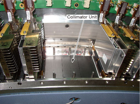
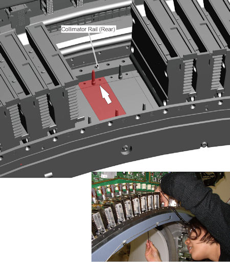
- Remove 3 detector modules (one is over the collimator unit and
the others are on both sides of it) as shown in Detector Module Replacement.
Figure 1. Collimator Unit
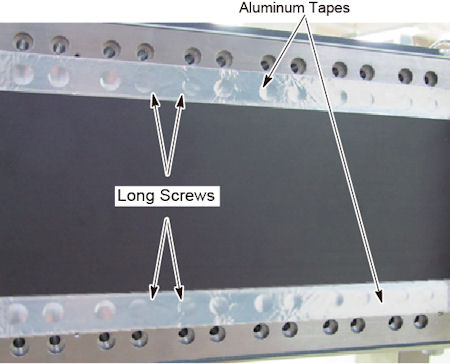
- Remove 4 long screws holding the collimator unit to the collimator
rails. Aluminum tape needs to tear off.
Figure 2. 4 Long Screws
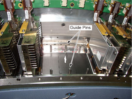
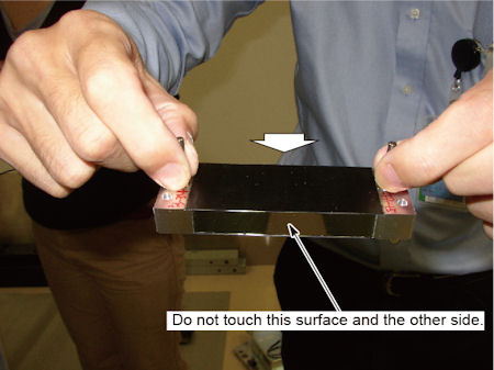
- Hold both guide pins of the collimator unit, and carefully pull
up the collimator unit.
Figure 3. Collimator Unit Removal
3 Installation Procedure
Procedure
- notice
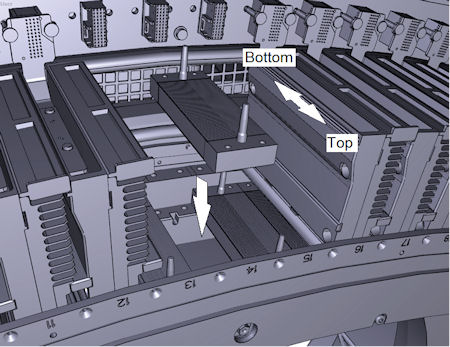
- Hold both guide pins of the collimator unit, and put it on the
collimator rails.
Collimator has its direction of top and bottom. Align the direction of top to gantry front.
Figure 4. Collimator Unit Installation
- Push the collimator unit against the rear collimator rail, and
tighten the 4 screws to fix the collimator unit to the collimator
rails.
Figure 5. Collimator Unit Fixing
- Install the 3 detector modules as shown in Detector Module Replacement.
- Check Aluminum tape condition. If Aluminum tape has been peeled off at the edge of carbon window, attach Aluminum tape to the area (Aluminum tape is provided with the FRU kit).
- Install the air plenum as shown in Detector Air Plenum Removal/Installation.
- Remove the cloth or any other item from the tube collimator port.
 |
4 Gantry Reassembly
Procedure
- Make sure the Axial Drive, HVDC and 120 VAC switches on the gantry’s Service Switch Panel are OFF.
- Release the gantry rotational lock and install gantry covers,
all except the right side cover.
Refer to Replacement → Gantry → Enclosure → (Cover Removal Procedures).
- Turn on the 120 VAC, HVDC and Axial drive service switches.
- Install gantry right side cover.
5 Finalization
Procedure
- Perform the Quality Assurance Test.
- Perform a [Save State] to save the new calibration data.
- Fill out the “Field Return Data Form” included with the FRU.
- Return the defect part with the form.