- Topic ID: id_15460186
- Version: 3.0
- Date: Jan 20, 2020 8:32:43 PM
DCB and DIFB Replacement
Prerequisites
Overview
This procedure defines the necessary steps to remove and replace a DCB or DIFB card.
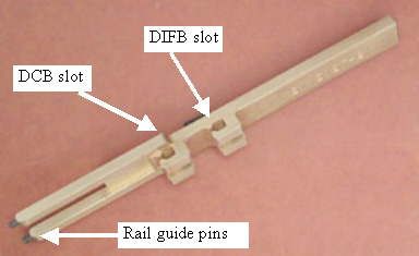
Figure 1. DCB/DIFB Card Ejection Tool (VDAS ONLY)
1 Card Access
Procedure
- Remove gantry right side cover.
Refer to
- Stop the rotor of X-ray tube in case of Liquid Bearing Tube before HVDC off. Refer to Liquid Bearing Tube Rotor stop procedure for details.
- Disable Axial drive and HVDC on the service switch panel.
- Position the gantry for easy access to the DIFB chassis required and lock gantry rotation.
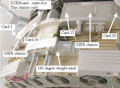
- The DCB and DIFB cards are located behind the DAS on either
side of the 180 degree weights. See Figure 2 - VCT DAS Side View.
Figure 2. VCT DAS Side View
- Disable gantry 120 VAC from the service switch panel.
- Remove the top cover for easier access to the DIFB chassis.
- Remove/loosen the cover screws on the top of the DIFB chassis.
See Figure 3 - DCB/DIFB Chassis Top View.
Figure 3. DCB/DIFB Chassis Top View
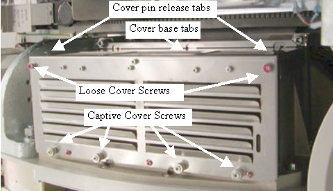
- Grab the cover on both sides using your thumbs to press in on the cover pin release tabs and lift the cover straight up and off the chassis. The tabs push a spring-loaded pin in the chassis frame. The cover is kept in line with the chassis by side channels in the chassis.
2 Card Removal
Procedure
- If removing the DCB, first disconnect the 2 fiber optic connections from the front side of the DAS plate.
- Remove the DAS board (DCB or DIFB) as required.
- Grab the board by the metal tab and pull away from backplane
connector to remove board.
On VDAS64 systems, the cards are very close together. The Ejection tool can be used to pull out the card if you can not grab the metal tab with your fingers. Do NOT use the ejection tool on HDAS systems as damage to components on the board can occur.
Figure 4. Ejection Tool Use for VDAS ONLY
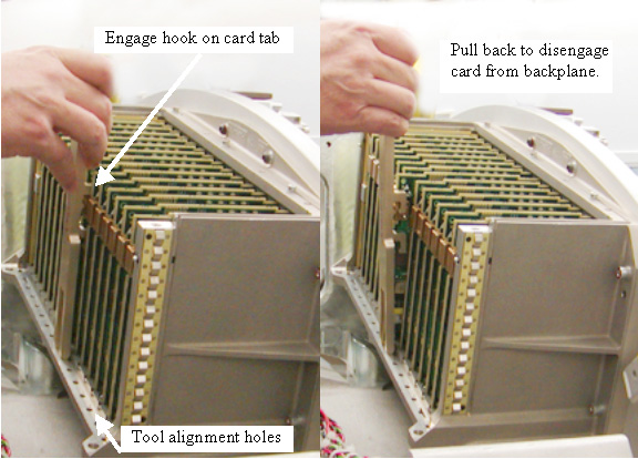
- Remove the board from the chassis.
- Grab the board by the metal tab and pull away from backplane
connector to remove board.
3 Card Installation
Procedure
- Insert the new card and push in on the card tab with your finger
to seat the card into the backplane connector. You may need to shift
the card up/down in the card guide slightly to align the connector.
Gentle pressure is all that is needed to seat the connector in the
backplane once the connector is aligned.note:
Do NOT use the ejection tool to install the new board as excessive force can damage the connectors.
- If installing a DCB, reinstall the fiber optic cable connection.
- Turn on the Gantry 120 VAC service switch and press the drives reset button on the service switch panel.
- Run the Flash download tool to make sure the card replaced is
running the latest firmware. A console pop up message may also indicate
that this is required after turning the DAS back on. Watch the LED's
to make sure status is consistent after a reset is completed.note:
The LED's of the new board may not flash in the same pattern as the existing boards until the Flash Download is performed.
- Turn off the Gantry 120 VAC service switch.
- Install the DIFB card cage cover making sure the cover base tabs are in the slots at the base of the chassis.
- Install the 4 captive cover screws and Torque to:
Install the 2 M6 cover screws and Torque to:
- Install the gantry top cover.
- Turn on the Gantry 120 VAC, HVDC and Axial Drive service switches on the service switch panel.
- Install the gantry right side cover.
4 Finalization
Procedure
- Run the System scanning test from the Functional Checks procedure list.