- Topic ID: id_15460178
- Version: 3.0
- Date: Jan 20, 2020 8:32:15 PM
DAS and Detector Air Filter Replacement
Prerequisites
Overview
This procedure defines the necessary steps to replace the DAS/Detector Air Filter.
1 Initial Steps
Procedure
 danger
- Remove right side gantry cover.
Refer to
- Stop the rotor of X-ray tube in case of Liquid Bearing Tube before HVDC off. Refer to Liquid Bearing Tube Rotor stop procedure for details.
- Disable Axial Drive and HVDC on the service switch panel then remove the gantry left side, top and front covers.
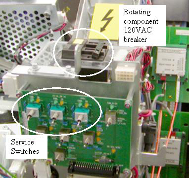
- Shut down power to the rotating assembly using the AC power
switch on the service switch panel. See Figure 1 for Rotating Assembly Power Breaker.
Figure 1. Rotating Assembly Power Breaker
2 Removal Procedures
Procedure
- notice
- Position the DAS at 12 o’clock and lock gantry rotation.
- Remove the plenum using the VCT Detector Air Plenum Removal and Installation procedure.
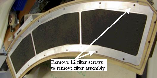
- Remove the filter assembly from the back of the air plenum and
reinstall new filter assembly. See Figure 2.
The filter assembly is attached to the rear of the plenum. The back side of the filter is an EMC screen that can be damaged if poked or hit. Be very careful with the new filter assembly.
Figure 2. Air Filter
3 Plenum Installation
Procedure
- Install the plenum using the VCT Detector Air Plenum Removal and Installation procedure.
4 Finalization
Procedure
- Install the gantry front, top and left side covers.
Refer to
- Enable 120 VAC HVDC and Axial Drive service switches from the service switch panel. Press the table drives enable button on the lower right corner of the service switch panel.
- Install the gantry right side cover.
- Wait for the detector temperature to return to normal.
- Perform a Fastcal.