- Topic ID: id_11038714
- Version: 4.0
- Date: Apr 22, 2019 12:56:11 AM
Collimator Filter Removal and Replacement
Prerequisites
Overview
This procedure documents how to remove and replace the collimator filter assembly.
Procedure
- Disconnect the CCB Chassis assembly. See Collimator Control Board Replacement procedure
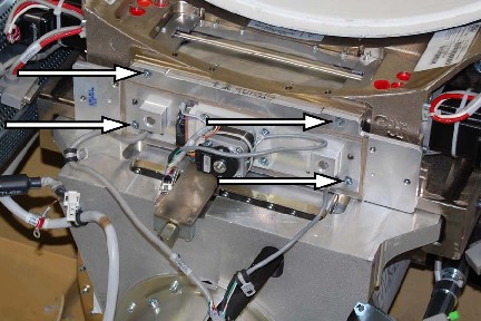
- Remove the (4) filter assembly mounting screws and remove the
assembly. Retain these screws for re-installation of the filter assembly.
Figure 1. Mounting Screw Locations
 note:
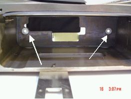
note:Collimator assembly will have two guide pins. The pins are used to position the collimator inside the frame properly. The filter will fit tightly, with no gap, when the pins are properly aligned.
Figure 2. Frame locator holes for guide pins
- Insert the filter assembly into the frame
- Secure new filter assembly to frame using only (4) M4-0.7, X10mm Long Socket Cap screws (GE P/N 1000-M4C010-04)
with lock and flat washers. Torque the mounting screws to 3 N-m (26.6
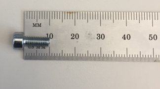
lb-in, 2.2 lb-ft) (Ref GE drawing 5222000ADW). If there is a question
whether the screw is the proper length, measure the shaft of the screw
only, not the head. The proper way to measure the length of a bolt
is depicted below:
Figure 3. Proper way to measure screw length. (10mm screw shown)
- Reattach the Collimator Control Board (CCB) Chassis assembly. See CCB Replacement