- Topic ID: task_phr_tnp_fnb
- Version: 2.0
- Date: Nov 26, 2020 8:38:13 PM
Anzai Respiratory Gating System Installation
Prerequisites
Overview
-
Install components in accordance with Figure 6.
-
Connect Load cell Sensor to Sensor Port.
-
Turn Sensor Port Power On.
-
Turn Laptop Power On.
-
Start Anzai Respiratory Gating software.
-
Perform Functional Tests.
1 Anzai Gating System Installation
Procedure
- Install the Anzai gating system according to Figure 6.
Figure 6. Anzai Respiratory Gating System Cable Connections

- Make sure Laptop Power is off.
- Connect Ethernet cable from Laptop to port 3 (RPM) of switching hub in CT console.
- Insert USB cable into (any) USB port on the Laptop and connect opposite end to Relay Box.
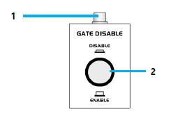
- Connect GDSW cable between Gate Disable Switch and Relay Box.
- Connect ground cable from Sensor Port to Accessory Panel (Gantry).
- Connect one AC IEC Power Adapter to Console AC outlet.
- Connect Laptop Power Supply cable to AC Power Adapter Cable (IEC) at Accessory Panel (Gantry) or Console AC Distribution box.
- Connect Laptop Power Supply to Laptop power input jack.
- Make sure Sensor Port Power is off.
- Connect the second AC IEC Power Adapter to Gantry AC outlet.
- Connect Sensor Port AC power cable to AC Power Adapter (IEC) cable at Accessory Panel (Gantry) or Console AC Distribution box.
- Connect AC power cable to back of Sensor Port.
- Connect Relay Box and Accessory Panel Respiratory jack on Gantry using EXT I/O Cable and Gantry Cable.
- Connect SP-RB I/O cable between Sensor Port and Relay Box.
- Discard cables that are not used in this configuration.
2 Initial Power Up
After all cable connections have been completed, proceed to turn power on as follows:
Procedure
- Connect load cell to CH1 Sensor Connector on the Sensor Port.
- Turn ON the power of Sensor Port.
- Turn ON the power of Computer. (Windows 10 will boot up).
- From the Window 10 Desktop select the AZ733VI icon to launch the application.
- Perform an initial test of the Load Cell Sensor by pressing it lightly between your fingers while observing the indicators on the top of the Load Cell Amp Box.
Notice that the indicator will change from LOOSE to GOOD to TIGHT when varying the amount of pressure applied. If this does not occur check cables and the possibility of a bad Load Cell Sensor. Make sure that the waveform changes with the amount of pressure is displayed on LCD Panel of Sensor Port.
Refer to Figure 7.
Figure 7. Initial Sensor Port and Load Cell Sensor Test Indicator
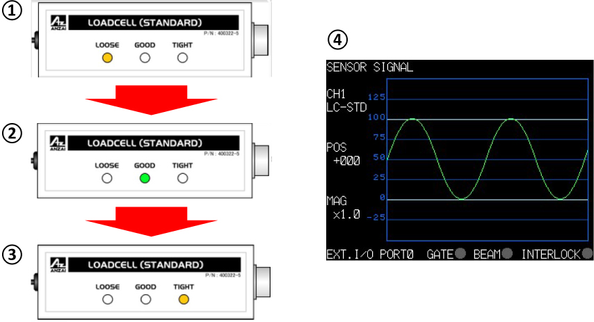
1 "Loose" lights up 2 "Good" lights up 3 "Tight" lights up 4 Waveform changes with the amount of pressure
3 Anzai Respiratory Gating System Functional Test
Procedure
- Select: "Test" and output Test Signal. Then, adjust Test Singal Respiratory Waveform.
Figure 8. Adjustment of Test Signal Respiratory Waveform
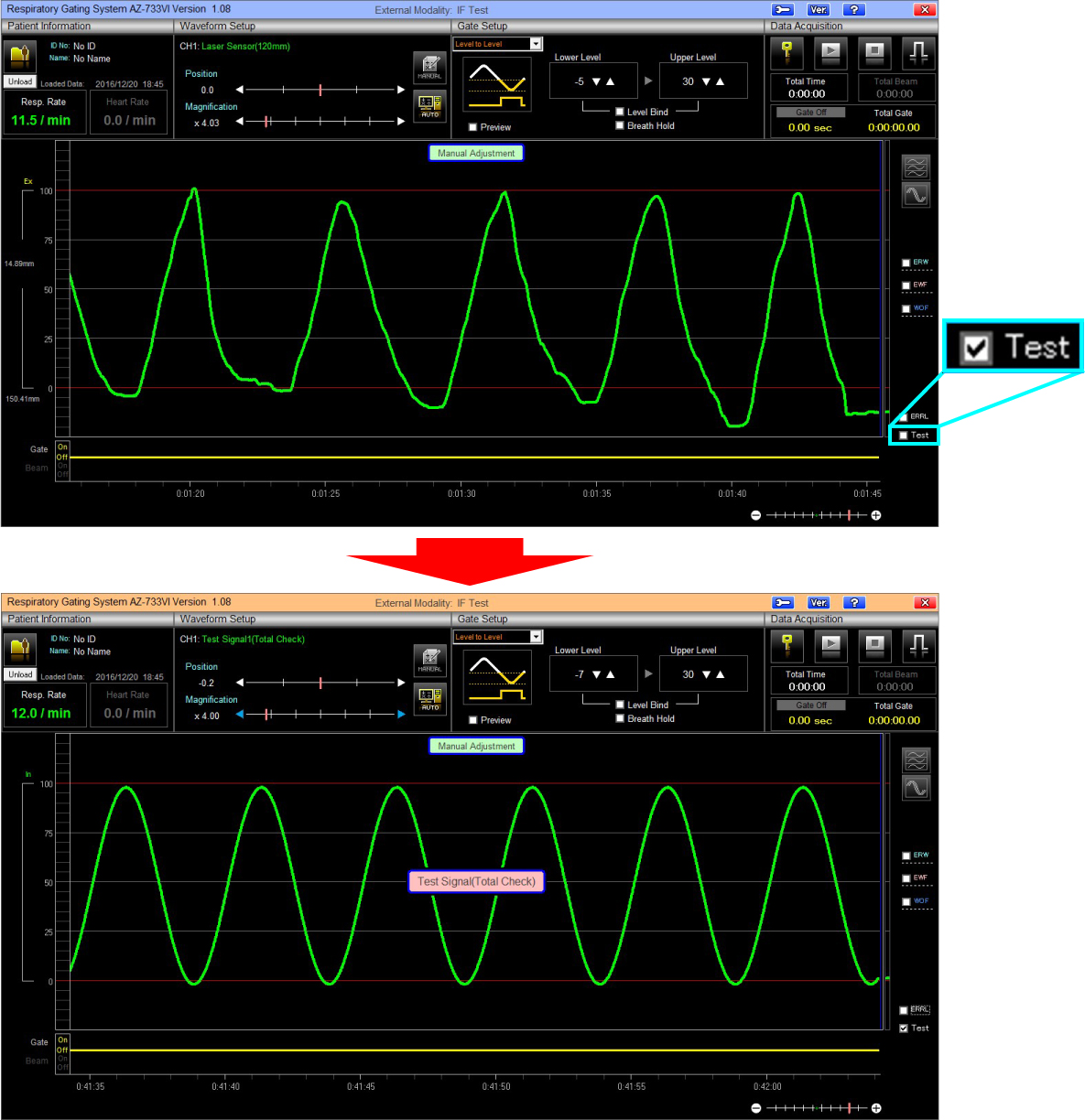
- At this point a test message “Test Signal (Total Check)” should be displaying at the center of the display. (Indicating the unit is using the internal test signal.)
- Adjust Position value and Magnification value so that the level of respiratory waveform is displayed between the level 0~100.
Figure 9. Waveform Setup
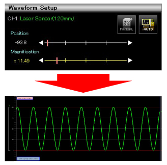
- Click “AUTO” icon to automatically adjust the Position and Magnification parameters. The green waveform will eventually settle itself between the red lines.
- This concludes the functional test of the simulated waveform.
4 Anzai Load Cell Sensor Functional Test
Procedure
- Uncheck: Test ....
- At this point the test message “Test Signal (Total Check)” will disappear from the center of the display.
- Insert the Load Cell Sensor into the belt pocket. (Either direction is OK for this test.) See Figure 10.note:
Either direction is OK for this test. For customer use, the Load Cell Sensor should be placed into the pocket with the curved side facing towards the chest.
Figure 10. Load Cell Sensor Operation

- Select "Setting Lock" icon.
Figure 11. Setting Lock icon

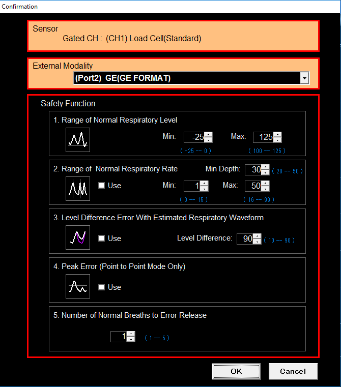
- Select [OK].
Figure 12. Confirmation Window
- Select [Start] icon to start respiratory acquisition.
Figure 13. Start Icon

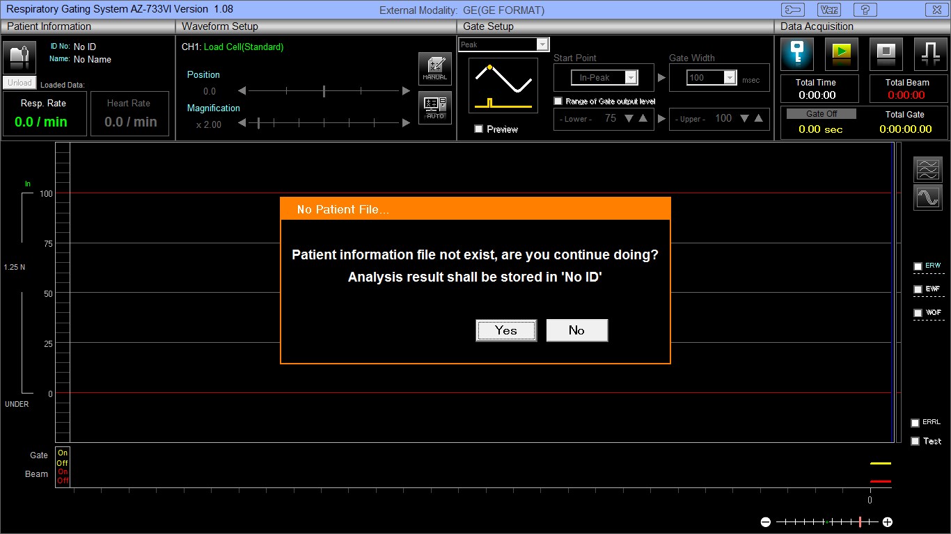
- If New Patient File does not exist, select [Yes] to continue.
Figure 14. No Patient File
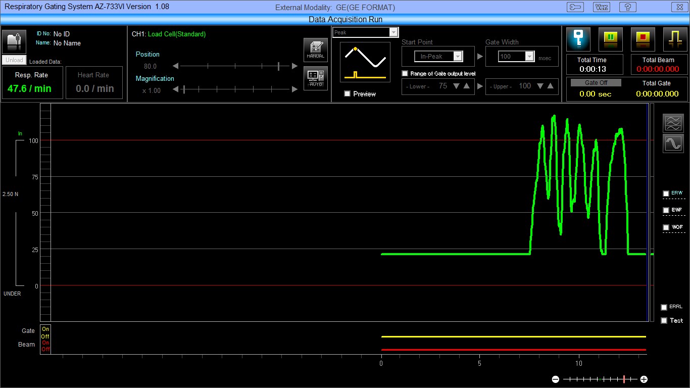
- A green waveform will begin tracking across the display.
- Gently press the load cell in the belt between your fingers and observe that the waveform changes with the amount of pressure applied.
Figure 15. Observing Waveform
- DO NOT stop the acquisition. Resume with next section, X-Ray On Signal Test.
5 X-Ray On Signal Test
Procedure
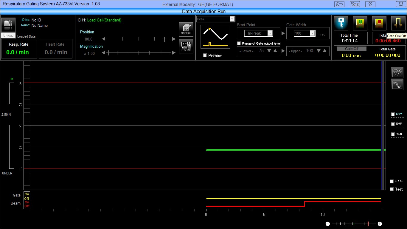
- Observe that the Total Time (in White) is counting.
- Observe that the Total Beam (in Red) is not counting and that the Red line (Beam) at the bottom of the display is a straight line (low) at the bottom of the display.
- At the front of the Relay Box, disconnect “EXT I/O cable (Dsub15⇒9 for GE)” from the Slot 2.
- Verify that the Total Beam (in Red) is now counting and that the Red line (Beam) at the bottom of the display has jumped to a High state.
Figure 16. Verify Total Beam
- Reconnect the cable to the “EXT I/O” connector and verify the that the Total Beam (in Red) counter has stopped, and the Red line (Beam) at the bottom of the display has returned to a Low state.
- Select the [Stop] icon.
Figure 17. Stop Icon

- Select [No] when the next dialog box (Save Results) appears.
Figure 18. Save Result

- This completes the test:
- If there was not a good indication of proper function, check all cables and repeat the tests.
- If the Customer is not going to use the system, exit the AZ-733VI Respiratory gating application.
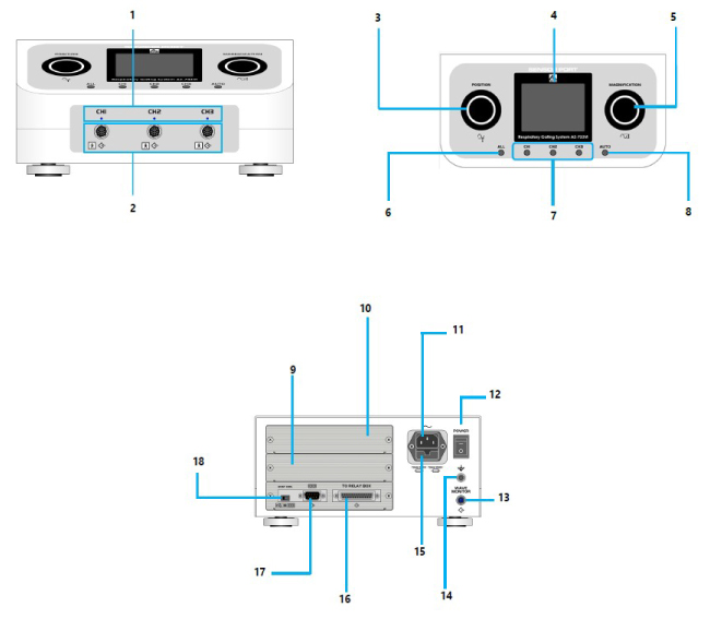
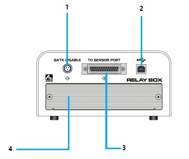
6 Appendix A: Indicators and Cable Connector Descriptions
Procedure
- Refer to following figures and tables, for definitions, Connector functions, and cable locations.