- Topic ID: id_2030109
- Version: 3.0
- Date: May 20, 2022 6:20:17 AM
AVIMOS Installation and Set Up
Prerequisites
note: Properly store the eye chart and the semi-transparent film as they are used during the replacement and alignment process.
1 AVIMOS installation and set up
Prerequisites
 |
|
Procedure
- Power ON the AVIMOS computer power. When the monitor light comes on and GE logo displays, press Ctrl+G+E simultaneously within 5 seconds.
- Enter User Name and Password (root user and its password) to access the AVIMOS service tool.
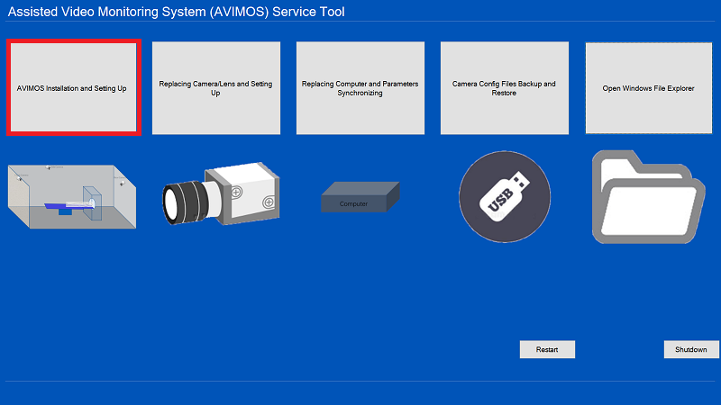
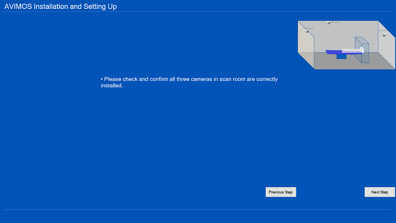
- Select AVIMOS Installation and Setting Up, if three cameras are correctly installed in scan room, click Next Step.
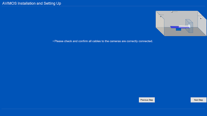
- If all cables are correctly connected, click Next Step.
- To adjust the side camera, click Next Step.
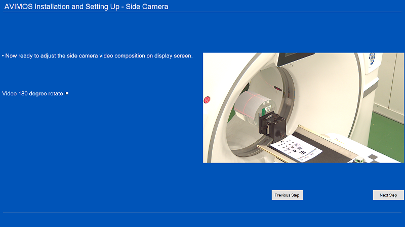
- When the side camera adjustment procedures display on the monitor, follow them to adjust the side camera. Click Next Step.
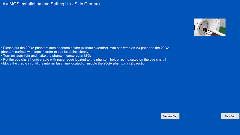
- Put the 20QA phantom onto phantom holder (without extender). You can wrap paper on the 20QA phantom surface with tape in order to see laser line clearly.
- Turn on laser lights and move the phantom to ISO center.
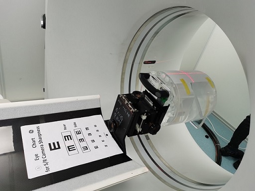
- Put the Eye Chart 1 onto cradle with paper edge located to the phantom holder as shown.
Figure 1. Eye Chart 1
- Move the cradle in until the internal laser line located on middle the 20QA phantom in Z direction.
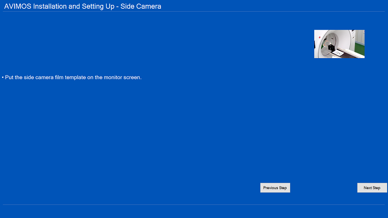
- Put the side semi-transparent film template on the monitor screen and click Next Step.
- Follow procedures on the monitor screen to adjust the side camera.note: Dim the scan room lighting equivalent to what the customer would use to align the patient with lasers.
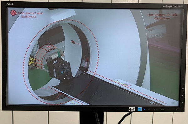
- Adjust the camera position by manually manipulating the camera on the bracket until the template circle and bore align along with the center line of the table.
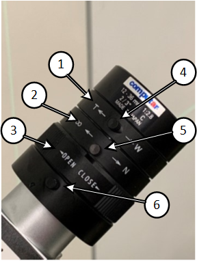
- Use the lens aperture ring to adjust the brightness of the image and lens zoom ring to size the image, use the sharpness ring to focus the image.note: This process is iterative and may take a few attempts. Final sharpness adjustment of the image is done in a later step.
- Observe the monitor screen, once the characterized target displays clearly into the expected area marked by the red dotted lines/circles, lock all adjusters, and then click Next Step.
Figure 2. Example of red dotted areas 1 through 4
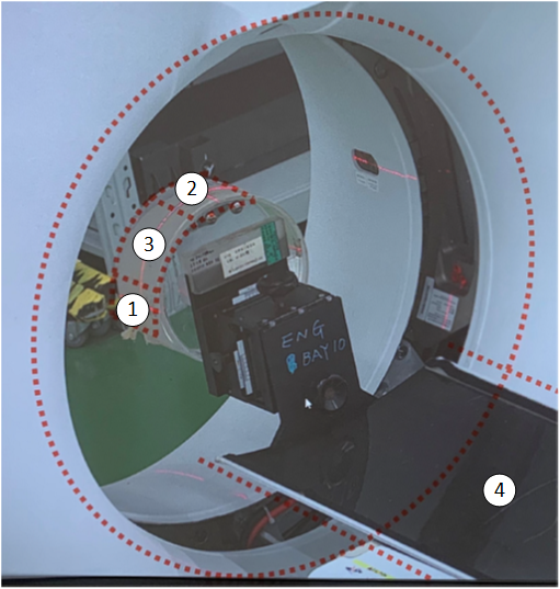
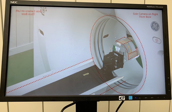
Figure 3. Proper side camera position (left)
Figure 4. Proper side camera position (right)
- Adjust the camera position by manually manipulating the camera on the bracket until the template circle and bore align along with the center line of the table.
- Remove the semi-transparent film template from the monitor.
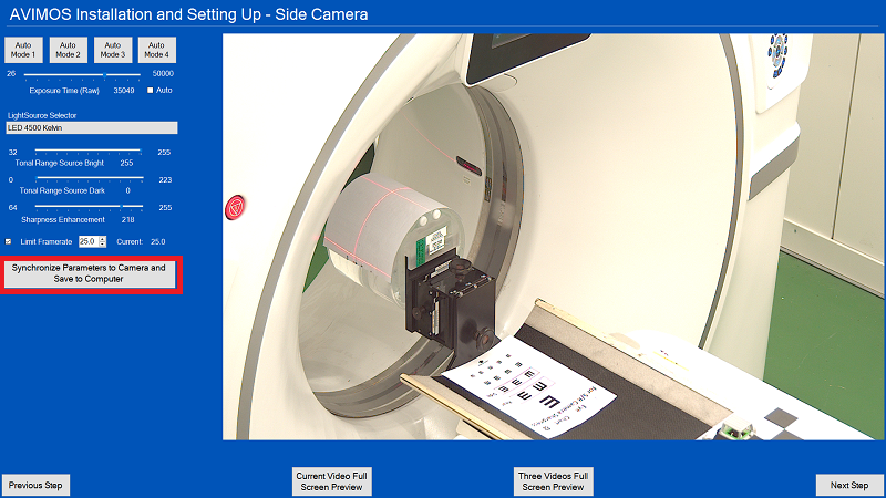
- Adjust parameters according to the site condition. Reference the following to see immediate results:
- Select Exposure Time (Raw) to decide the exposure time for camera. Generally if Auto is checked, it is OK.
- Select LightSource Selector according to site room light condition. Generally LED 5500 Kelvin is OK, but you can select others according to site YELLOW/WHITE light condition.
- Select Tonal Range Source Bright value. Generally 255 is OK.
- Select Tonal Range Source Dark value. Generally 0 is OK.
- Select Sharpness Enhancement value. Generally 180 is OK.
- Select Limit Framerate value.
- Generally set Limit Framerate to 25 for non-Revo systems such as Revolution HD / Revolution Frontier, Optima CT520/CT540/CT620/CT670/CT680/CT660/EVO, Revolution Maxima, Tai-16, Revolution ACT, NGX/NGX-F.
- Generally set Limit Framerate to 20 for Revolution CTES and Revolution Apex system because Revo systems.
note: You can also select one of the Auto Mode buttons, which provides suggested LightSource Selector, Sharpness (180), and Limit Framerate values.
- Select Synchronize Parameters to Camera and Save to Computer button, once successful, and then click Next Step.
- To adjust the rear camera, click Next Step.
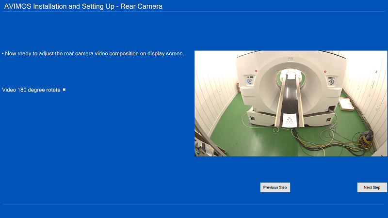
- When the rear camera adjustment procedures display on the monitor, follow them to adjust the rear camera. Click Next Step.
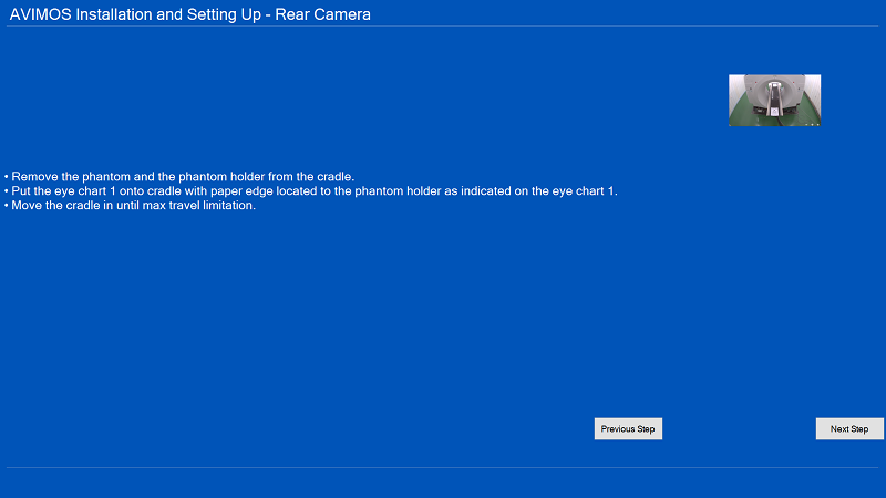
- Remove the phantom and the phantom holder from the cradle.
- Put the Eye Chart 1 onto cradle with paper edge located to the phantom holder as shown in Figure 1.
- Move the cradle in until the maximum travel limitation is reached.
- Put the rear semi-transparent film template on the monitor screen, click Next Step.
- Follow procedures on the monitor screen to adjust the rear camera.
- Turn on internal laser lights.
- Place eye chart on the table, positioning the table and chart so it is fully in view of the rear camera.
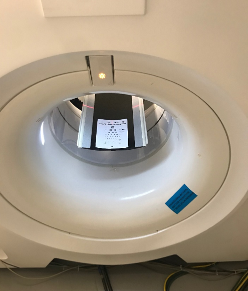
- Use the camera lens sharpness and zoom rings to adjust until the indicated sharpness line is seen.
- Tighten the sharpness and zoom locking screws on the camera lens.
- Observe the monitor screen, once the characterized target displays clearly into the expected area marked by the red dotted lines/circles, lock all adjusters, and then click Next Step.
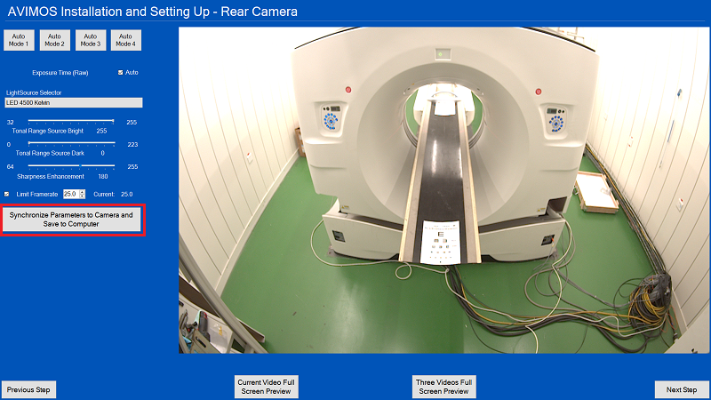
- Adjust parameters according to the site condition. Reference the following to see immediate results:
- Select Exposure Time (Raw) to decide the exposure time for camera. Generally if Auto is checked, it is OK.
- Select LightSource Selector according to site room light condition. Generally LED 5500 Kelvin is OK but you can select others according to site YELLOW/WHITE light condition.
- Select Tonal Range Source Bright value. Generally 255 is OK.
- Select Tonal Range Source Dark value. Generally 0 is OK.
- Select Sharpness Enhancement value. Generally 180 is OK.
- Select Limit Framerate value.
- Generally set Limit Framerate to 25 for non-Revo systems such as Revolution HD / Revolution Frontier, Optima CT520/CT540/CT620/CT670/CT680/CT660/EVO, Revolution Maxima, Tai-16, Revolution ACT, NGX/NGX-F.
- Generally set Limit Framerate to 20 for Revolution CTES and Revolution Apex systems.note: You can also select one of the Auto Mode buttons which provides a suggested LightSource Selector, Sharpness (180), and Limit Framerate values.
- Select Synchronize Parameters to Camera and Save to Computer button, once successful, click Next Step.
- To adjust the front camera, click Next Step.
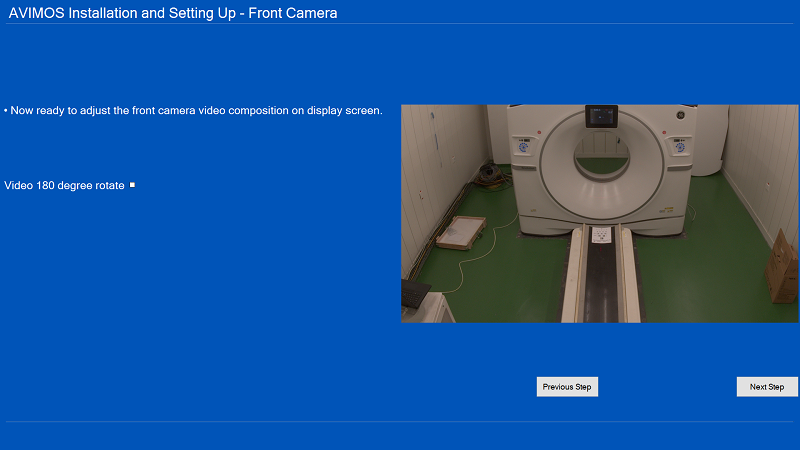
- When the front camera adjustment procedures display on the monitor, follow them to adjust the front camera. Click Next Step.
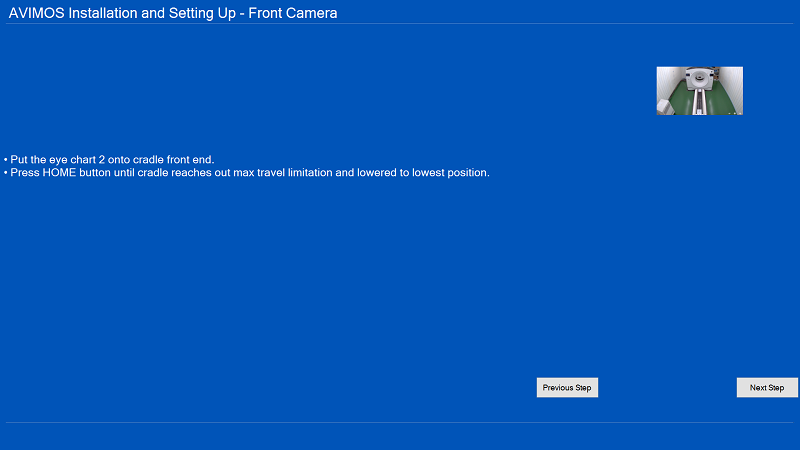
- Put the Eye Chart 2 onto cradle front end.
- Press HOME button until cradle reaches out max travel limitation and lowered to lowest position.
- Put the front semi-transparent film template on the monitor screen, click Next Step.
- Follow procedures on the monitor screen to adjust the front camera.
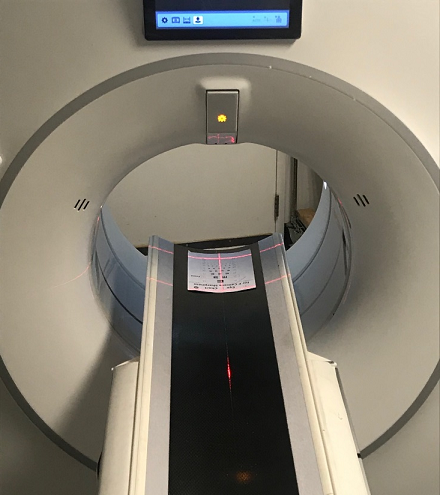
- Turn on internal laser lights.
- Place eye chart on the table, positioning the table and chart to the indicated laser alignment lines on the chart.
- Use camera lens to sharpness and zoom rings to adjust until the indicated sharpness line is seen.
- Tight the sharpness and zoom locking screws to the camera lens.
- Observe the monitor screen, once the characterized target displays clearly into the expected area marked by the red dotted lines/circles, lock all adjusters, and then click Next Step.
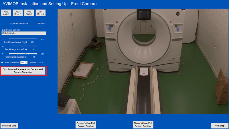
- Adjust parameters according to the site condition. Reference the following to see immediate results:
- Select Exposure Time (Raw) to decide the exposure time for camera. Generally, if Auto is checked, it is OK.
- Select LightSource Selector according to site room light condition. Generally, LED 5500 Kelvin is OK, but you can select others according to site YELLOW/WHITE light condition.
- Select Tonal Range Source Bright value. Generally 255 is OK.
- Select Tonal Range Source Dark value. Generally 0 is OK.
- Select Sharpness Enhancement value. Generally 180 is OK.
- Select Limit Framerate value.
- Generally set Limit Framerate to 25 for non-Revo systems such as Revolution HD / Revolution Frontier, Optima CT520/CT540/CT620/CT670/CT680/CT660/EVO, Revolution Maxima, Tai-16, Revolution ACT, NGX/NGX-F.
- Generally set Limit Framerate to 20 for Revolution CTES and Revolution Apex systems.
note: You can also select one of the Auto Mode buttons which provides suggested LightSource Selector, Sharpness (180), and Limit Framerate values.
- Select Synchronize Parameters to Camera and Save to Computer button, once successful, click Next Step.
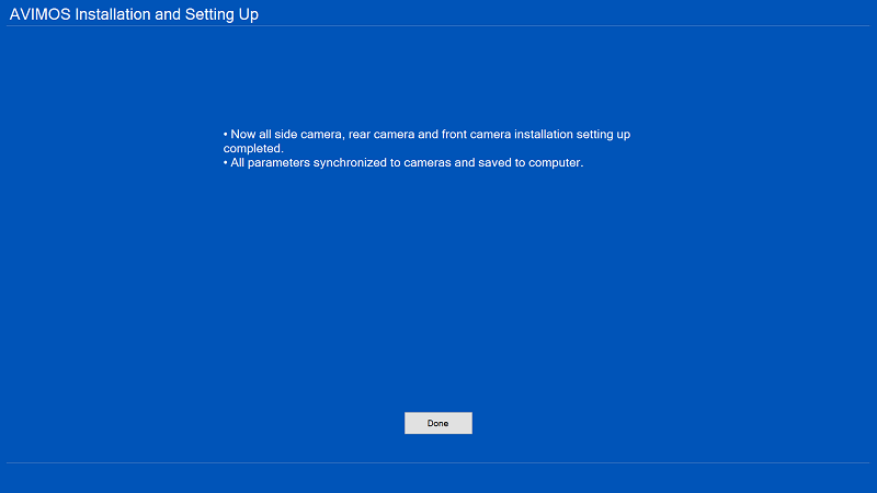
- When all camera set up is completed, click Done.
- Shutdown the AVIMOS system.
- Disconnect and remove the three (3) JIG cables, and RT45 to RJ45 connectors.
- Move the AVIMOS computer and the LCD monitor to the location on the console desk near the system monitors.
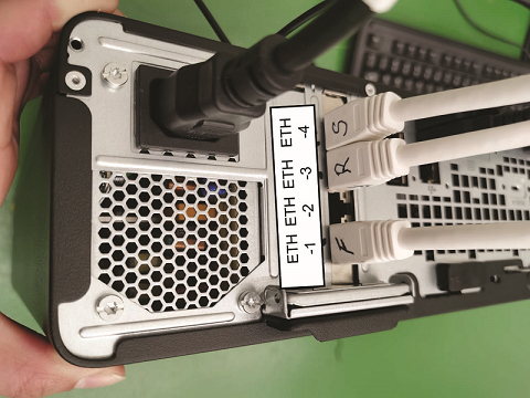
- Connect the three (3) camera cables to the AVIMOS computer.
- Power ON the AVIMOS computer power.
- Retain the eye chart and the semi-transparent film.note: Properly store the eye chart and the semi-transparent film as they are used during the replacement and alignment process.