- Topic ID: id_16157858
- Version: 4.0
- Date: Jan 20, 2020 8:36:20 PM
5114128 Cable Replacement
Prerequisites
Overview
Procedure
- Raise the Table to maximum height.
- Perform this step if applicable:
(For Global PET/CT Table, with fixed position IMS) Move the Cradle to OUT limit position.
(For Global PET/CT Table) Move the Cradle and IMS to OUT limit position.
(For GT1700 and GT2000 Table) Move the Cradle and IMS to OUT limit position.
(For GT1700V Table) Move the Cradle to OUT limit position.
- Remove power from Table by turning off 120VAC, Axial Drive and HVDC switches on Service Switch Panel.
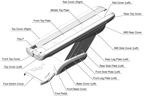
- Remove the following Table covers:
-
Top Cover (Left)
-
IMS Rear Cover
-
IMS Side Cover (Left)
-
Front Side Plate (Left)
-
Rear Side Plate (Left)
-
Front Base Cover
Figure 1. Table Covers
-
- Cut any tie-wraps holding the cable (5114128 ) to the Table frame.
- Disconnect the cable connectors (5114128 - Cradle Motor Driver ↔ J204, Connector).
- Remove the cable(s) from the Table.
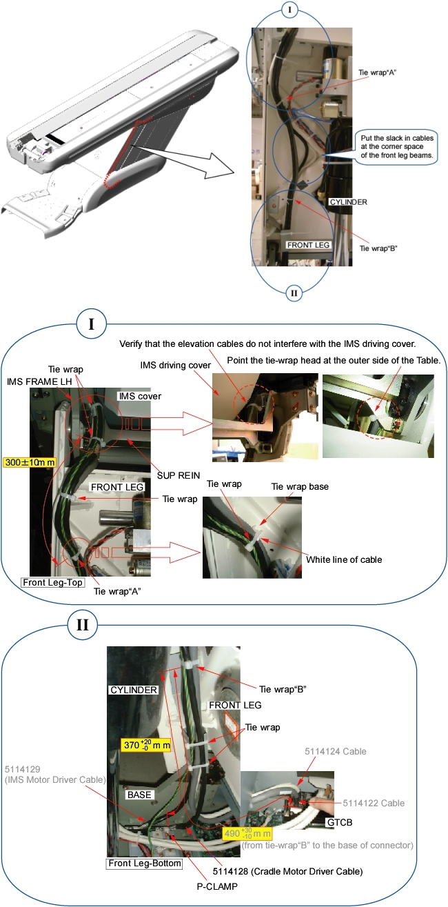
- Route the new cable(s) along the inside of the front leg assembly
just like the old cable(s) (see illustration below).note:
IMS Driving cover and 5114129 (IMS Motor Driver Cable) not present on Global PET/CT Table, with fixed position IMS and GT1700V Table.
Figure 2. Cable Routing
- notice
- Connect the cable connectors, and fasten the cable(s) to the Table frame with tie-wraps (see Figure 2).
- Perform this step if applicable:
(For Global PET/CT Table, with fixed position IMS) Skip this step.
(For Global PET/CT Table) Verify that the cable connector does not interfere with IMS movement.
(For GT1700 and GT2000 Table) Verify that the cable connector does not interfere with IMS movement.
(For GT1700V Table) Skip this step.
 |
Finalization
- Power up the Table from the Service Switch Panel.
- Verify that the Table moves up and down normally.
- Turn off all 3 switches (Axial Drive, HVDC, 120VAC), and re-install the Table covers.