- Topic ID: id_15460389
- Version: 4.0
- Date: Jan 20, 2020 8:36:31 PM
5114122 Cable Replacement
Prerequisites
Overview
Procedure
- Raise the Table to maximum height.
- Move the Cradle and IMS to OUT limit position.
- Remove power from Table by turning off 120VAC, Axial Drive and HVDC switches on Service Switch Panel.
- Remove the following Table covers:
-
Top Cover (Left)
-
IMS Rear Cover
-
IMS Side Cover (Left)
-
Front Side Plate (Left)
-
Rear Side Plate (Left)
-
Front Base Cover
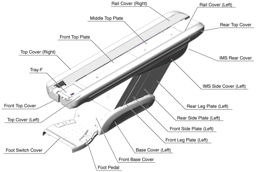
Figure 1. Table Covers
-
- Cut any tie-wraps holding the cable (5114122 / 5114124) to the Table frame.
- Disconnect the cable connectors as follows:
-
5114122 - (J11, GTCB Assy ↔ J200, Connector)
-
-
-
- Remove the cable(s) from the Table.
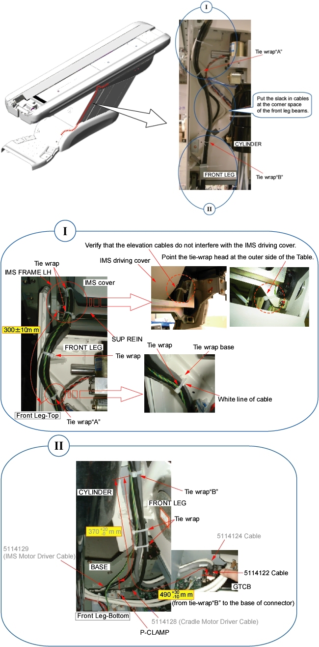
- Route the new cable(s) along the inside of the front leg assembly
just like the old cable(s) (see illustration below).
Figure 2. Cable Routing
- notice
- Connect the cable connectors, and fasten the cable(s) to the Table frame with tie-wraps (see Figure 2).
- Verify that the cable connector does not interfere with IMS movement.
 |
Finalization
- Power up the Table from the Service Switch Panel.
- Verify that the Table moves up and down normally.
- Turn off all 3 switches (Axial Drive, HVDC, 120VAC), and re-install the Table covers.