- Topic ID: id_18480146
- Version: 2.0
- Date: Dec 21, 2018 2:36:28 AM
SDCB DAS Troubleshooting
1 Overview
The number of the detector AD modules connected to one DAS Interface block was changed from 4 on HDAS to 14 on SDCB DAS. This design change made troubleshooting of the communication failure between DAS and AD modules difficult. This procedure provides information of effective troubleshooting for the communication failure.
2 Procedure
2.1 Problem Description
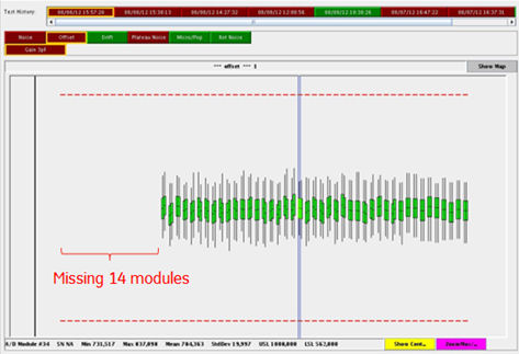
There is a failure mode that DAS cannot detect multiple detector modules due to communication failure between SDCB and detector module. Typically, 14 modules (= one SDCB slave block) are not detected by SDCB.
The following is typical error message and DAS tool output caused by this failure mode.
Host : Das Ermes # : 260132793
Exception Class : Abort Severity : Primary
File : IFBManagerSdcb.cxx Line# : 1185
Function : No System Function Reported
Scan Type : None/Unknown Scan: 0/0/0
The Following Digital Modules Have Not Been Detected By The Data Acquisition System.
See Previous Messages From Last Reset For Detailed Fault Information.
Digital Modules: 1-14
Figure 1. DAS Tool (Offset test)
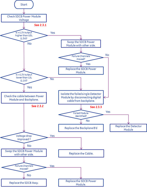
2.2 Troubleshooting Flow
Figure 2. Troubleshooting Flow
2.3 Troubleshooting Details
2.3.1 Check SDCB Power Module Voltage
Check +1.2V output from Power Module of the failed exams by RTS.
Figure 3. DAS RTS data example
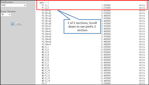
DAS Power Module voltage can also be checked by DAS tools Aux channels Test or Scan Data Path Manual test.
-
If any +1.2 output is higher than upper spec limit (+1.3V) and it corresponds to the missing modules, the problem may be caused by defective Power Module or Single Defective Detector module. The recommended action is:
-
Swap the Power Module with other side.
-
If the failure channels do not move, isolate the defective detector module according to the section 3.
-
-
If any +1.2 output is lower than spec limit (+1.1V) and it corresponds to the missing modules, the problem may be caused by defective Power Module or loose connection between Power Module and backplane. The recommended action is:
-
Check the cable between Power Module and Backplane. (Refer to section 2) )
-
Swap the Power Module with other side.
-
2.3.2 Check the cable between Power Module and Backplane
-
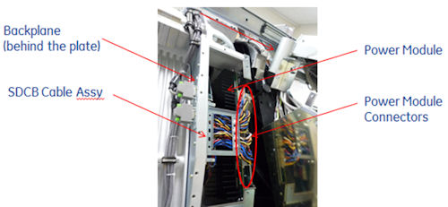
Check if the SDCB Cable is not pushed by DAS cover. Overstress to the cable could cause the power loss or voltage drop.
-
Disconnect and reconnect the SDCB cable between Power Module and Backplane.
-
If the voltage of Power Module is improved, the cable may be defective.
-
If the voltage of Power Module is NOT improved, the Power Module may be defective.
-
Figure 4. Power Module Connectors
2.3.3 Isolate the failed Detector Module by disconnecting digital cable from backplane
The SDCB-AD Module Communication Failure for 14 (or 15) modules could be caused by single detector module failure.
To identify which detector module (ADM) is defective, disconnect digital cable between detector module and backplane. When defective module is disconnected, all modules except the disconnected one will be detected by DCB.
To reduce iteration of disconnecting cable, try the following procedure.
(Assuming modules #1 -#14 are not detected).
-
Disconnect 7- digital cable between ADM1-7 and backplane. Then confirm the communication.
-
If communication between SDCB and ADM8-14 is OK, then defective ADM is in the group of ADM1-7.
-
If communication is still not established, then defective ADM is in the group of ADM8-14.
-
-
Disconnect the first 3 modules of the defective 7 module group.
-
If communication between SDCB and the last 4 ADMs is OK, then defective ADM is in the first 3 ADMs.
-
If communication is still not established, then defective ADM is in the group of the last 4 ADMs.
-
-
Repeat the same until isolating down to a single defective ADM.
It is not recommended to remove or swap the multiple detector modules. It will increase the risk of damaging the detector module.
The module digital cable connectors are always pushed
to the backplane connectors by spring. To keep the cable disconnected,
use any suitable clips or clamps to hold the cable. The following
picture shows an example of using binder clips.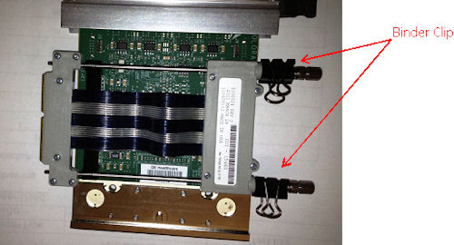
Refer to HDAS with SDCB Block Diagram and Channel map (Cj Phase 2.0) in Functional Interconnects to confirm the ADM# and corresponding SDCB slave block number.