- Topic ID: id_18480653
- Version: 2.0
- Date: Dec 21, 2018 2:36:12 AM
Real-In-One Console Theory
This module contains the following subsections:
-
Overview - Overview (Real-In-One Console)
-
Host Computer Z800 - Host computer z800
-
GPU (Graphic Process Unit) - GPU Card
-
Positioner Interface - Positioner Interface
-
RAID5 Theory - RAID Theory
-
Peripheral Media Tower - Peripheral Media Tower
-
Cooling System - Cooling System
-
Service and Diagnostics - Service and Diagnostics
-
Console Block Diagrams - Console Block Diagrams
1 Overview
The Real-In-One Console consists of the following components.
-
Host Computer - contains the System / Image Data Disks, FDIP board and five scan data disks structures RAID5 feature.
-
GPU: a graphic card is used for every reconstruction mode.
-
Intercom - Same electronic circuit board is used as GOC4 ICOM, but new PWA and bracket is newly introduced.
-
Cooling Package, including:
-
Fans
-
Air Filter
-
For RIO console, Host computer receives raw data from the Data Acquisition System (DAS) through an on-board Data Interface processor (FDIP) card, and stores that data in the Scan Data Disks located in the Host computer. The raw data is then delivered from the scan data disks in the Host PC to the IG processes in Host PC. The IG processes then create images (If GPU card is installed, GPU card will be utilized during BP reconstruction). The images generated are saved in image disk in host computer.
The host computer for the Real-In-One console will be an off-the-shelf, Linux-based system.
Key performance specification of the RIO console are:
-
Recon times: 6 fps with software BP, 16 fps with GPU BP
-
Image Matrix: < 512 x 512 pixels
2 Host Computer Z800
Host Computer in RIO console is the central operation controller of the CT system.
Host Computer controls all the RIO console functions and data flow, including actual image generation. Software in Host computer sends the reconstruction request, recognize the recon mode, timing, parameters, and data, and be able to generate the image set. The raw data is first restored from the disks. The Host Computer then creates an image set and requests image generation to the IG process in Host Computer. While most of the software components (e.g. Recon_Control, Data_Restore, Image_Buffer, and Data_Acq) reside on Host Computer, the components related to image generation also reside on Host Computer.
Main data flow of the Host Computer is described as follows:
-
Receive raw data from the Gantry
-
Store the raw data to the scan data disks
-
Restore the raw data from the scan data disks and transfer to buffer memory in Host Computer.
-
Take multi-image streams from Image generation processes ran on Host computer, and be saved on image disk in Host Computer.
The Host Computer is comprised of the following:
-
HP computer: a computer using a high-performance PC workstation
-
System disk: the OS and Applications software are stored on this disk
-
Image disk: Images are stored on this disk
-
Scan data disks: the raw data are stored on five scan data disks (RAID5).
-
FDIP card: the DAS Interface Processor card
-
Gigabit Ethernet (GbE) cards
-
DVD-ROM drive: will be used for software installation and stand-alone use
-
RAID card: connect to five scan data disks.
-
Graphics board: connect to two LCD monitors
-
GPU: an optional graphic card is used for 16 FPS image reconstruction, ASIR or Fluoro option.
2.1 Motherboard
The Host Computer will take advantage of a standard, off-the-shelf motherboard, using dual microprocessors to increase processing density. The Host Computer will use very high performance general-purpose processors, memory, and a server motherboard with GB Ethernet and SAS port(s), and power supply.
-
Dual Processors: Intel ® Xeon™ Quad Core processors or successor
-
Memory: 24GB FBD DDR3-1333 REG ECC DIMM
-
Onboard SAS Devices: four (4) SAS ports reside on mother board
-
Seven (7) PCI/PCI-X/PCI-E expansion slots.
-
SLOT 1PCI-E: FDIP card
-
SLOT 2 PCI-E: graphics card
-
SLOT 3 PCI-E: Dual Part Gigabit Ethernet card
-
SLOT 4 PCI-E: RAID Controller
-
SLOT 5 PCI-E: GPU card
-
SLOT 6 PCI: Not used.
-
SLOT 7 PCI-E: Dual Port USB 2.0 PCI card
-
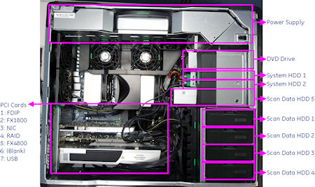
2.2 Component ID
The following picture show the Z800 panel and component ID.
Figure 1. Z800 Front Panel
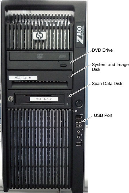
Figure 2. Z800 Rear Panel
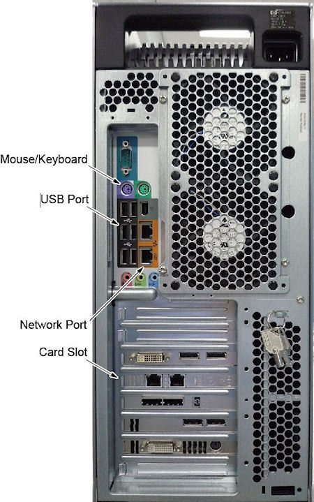
Figure 3. Mother Board
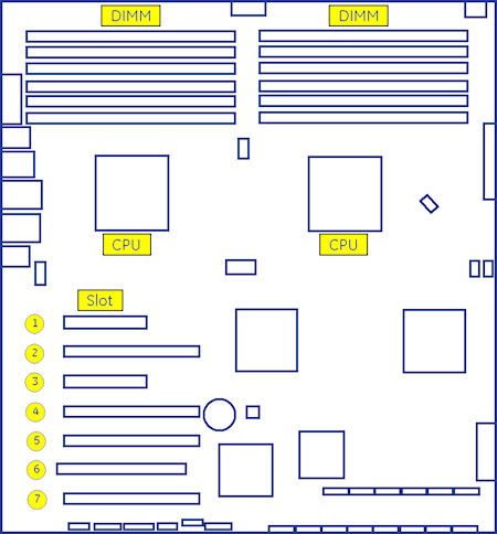
Figure 4. Z800 Left Side View
2.3 Disk Drives
There are two (2) SAS hard disk drives (146GB) and five (5) SAS hard disk drives for scan data connected to RAID card in Host computer. Below are the definition of these four hard disk drives:
-
SAS0: System disk
-
SAS1: Image disk
-
SAS3: Scan data disk 1
-
SAS4: Scan data disk 2
-
SAS5: Scan data disk 3
-
SAS6: Scan data disk 4
-
SAS7: Scan data disk 5
Below are key performance specifications of the system/image hard disk drives:
-
Minimum rotational rate of 10,000 RPM
-
SAS interface (3 Gigabits/second burst rate)
-
Formatted capacity of 146 Gigabytes
-
Form Factor: 2.5” half height form factor
Below are key performance of the scan data drives.
-
Minimum rotation rate of 15,000 RPM
-
SAS interface
-
Formated capacity of 300 Gigabytes
-
3.5” full height
Five Scan Data Disks are connected to the RAID card that enables hardware RAID5 (approximately 512 Gigabytes).
2.4 FDIP Card
This PCI FDIP card supports almost the same functionality as the current DIP in that it converts the optical signal received from the Gantry into electrical raw data and writes that data to one of the double buffers on the card. When the received data count reaches a predetermined value it will switch over to the other buffer. The Host Computer then receives this data via the PCI bus. This card supports 64bit, 66MHz, PCI bus interface with an FPGA, and should be able to support 833MB/sec data rate optical fiber interface.
2.5 Gigabit Ethernet Card
TGPU board in gantry is connected to the Host computer via Gigabit Ethernet (GbE) card connected to one of the PCI-X slots.
Gigabit Ethernet (GbE) card:
-
Dual Gigabit Ethernet ports
-
10Base-T, 100Base-TX, 1000Base-TX IEEE802.3ab compatible
-
64bit, 66MHz (or higher) PCI-X interface
-
Low profile form factor
Gigabit Ethernet card ports definition is described below:
2.6 USB Ports
The USB ports on Host Computer are used to connect the peripheral devices. The definition of USB ports is listed as below:
2.7 DVD-ROM Drive
The DVD-ROM drive is used for software installation, system diagnostics, and to support stand-alone operation of the Host computer.
3 GPU (Graphic Process Unit)
This PCI card accelerates the back-projection process of the RIO console and is plugged into PCI-e slot in the Host Computer.
This parallel beam back-projector provides the RIO console the ability to off-load the back-projection application from general-purpose processors to fully programmable hardware. This option dramatically increases the reconstruction performance per cost ratio.
Following are the high-level CTQs for the GPU card:
-
Perform parallel beam back-projection at >16fps
-
PCI-e compatible
-
Reconstruct any image matrix size up to 524,288 32bit pixels
4 Positioner Interface
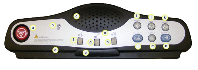
4.1 Scan Control Interface Module (SCIM)
The Scan Control Interface Module (SCIM) along with 101-key keyboard supplies the user with the necessary inputs for performing scans. The SCIM supplies a series of switches that allows the user to position the patient using Positioner (Gantry/Table) subsystem without leaving the console and entering the scan room. (See Figure 5 for SCIM functions.)
Figure 5. Scan Control Interface Module (SCIM)
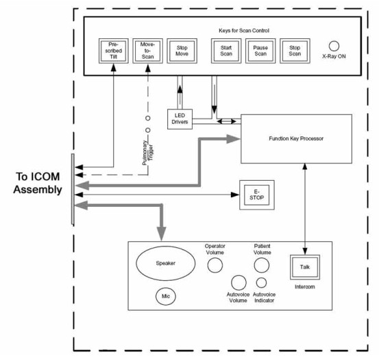
The SCIM connects directly to the ICOM assembly located in the RIO console to supply scan, intercom and safety features provided by the SCIM. (See Figure 6.
Figure 6. SCIM Block Diagram
4.2 Intercom (ICOM)
The Intercom (ICOM) assembly (lodated in AC Box Assembly) (Figure 7) translates five functions and miscellaneous signals between the console and gantry:
-
Bi-directional audio – Host Computer and SCIM
-
Table/gantry motion control – SCIM
-
Gantry reset – Host Computer
-
X-ray abort – FDIP Card
-
Console power indicator - ICOM
This information is sourced/received by the above computers and transferred through a single 25-pin cable to/from the gantry.
Figure 7. ICOM Assembly
4.2.1 Overview
The Intercom block enables communication between the console operator and the patient on the table. The communication direction through the Intercom can be switched by depressing the TALK button on the SCIM keyboard. The operator can speak to the patient by depressing the TALK button (ON). When the TALK button is released (OFF) the operator can then listen to the patient.
When Auto-voice is playing, the operator can listen through the Console speaker on the Auto-voice R channel while the TALK button is released (OFF). At the same time the patient can listen through the Table speaker on the Auto-voice L channel.
If the operator depresses the TALK button (ON) while Auto-voice is playing, the Intercom will disable the Auto-voice sound and will switch the sound source to the Console microphone output. The Console microphone output is amplified and routed to the Host computer's audio input for the Auto-voice recording. The Auto voice recording will be managed by the host computer's software. It will be up to the software to start and stop recording the sound.
4.2.2 Intercom Functional Block Diagram
Figure 8. Intercom Functional Block Diagram
4.2.3 Prescribed Tilt / Reset Circuit Operation
The Prescribed Tilt circuit block will detect the status of the TILT push button in the SCIM keyboard as it is pressed or released (NO - Normal Open; NC - Normal Closed respectively) by the use of two independent paths. An invert logic signal condition (XOR) in between these two paths is used to determine the tilt condition. The pulse width of both signals shall be the same when the push button is pressed. Once the signals are received, the dual signal (redundant path) will be transmitted to the TGP board so than a single point of failure will not cause tilt motion.
The Prescribed Tilt circuit performance requirements are specified in the following:
-
One push button switch double-pole double-throw. The button has six contacts. Contacts 1-3 are used for primary (Hardware) path. Contacts 4-6 are used for secondary (Firmware). See Figure 9.
Figure 9. Prescribed Tilt Requirements
-
The Prescribed Tilt block detects the condition of the DPDT button in the SCIM keyboard (either press or release) by using two independent paths. These two paths have an inverse logic condition between them and both signals must remain constant for the same period of time while the button is pressed.
-
No single wire can cause Tilt motion. If one of two wires fails, the circuit will not cause tilt.
-
The circuit receives dual signals and generates two independent differential signals that are sent to the TGP board. The output remains active as long as the button is pressed.
-
The defined Voltage level of the Prescribed Tilt signal is no greater than 5V.
The Reset block will receive and detect the serial break command from the Host computer serial port expander (RS-232), and then generate another pulse, which will be sent to the TGP board in the Gantry. Its performance requirements are illustrated below:
-
The Serial port expander interface sends a minimum RS-232 serial break command of 4mA and 8.1V in order to generate the Gantry Reset signal.
-
The Gantry Reset circuit responds to any pulse with a width longer than 200ms and will not respond to any pulse with a width less than 150ms.
-
Once the serial break command has been detected the output of the Gantry Reset circuit will be differential, an active high pulse signal, from 0VDC to +5VDC, with a width no less than 100ms.
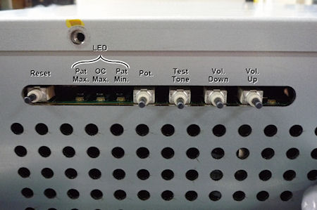
There are four LEDs and five Test Points (see Table 2) on the board to detect the errors in the events of Gantry Tilt and Reset failures.
-
In the Prescribed tilt circuit the LED Tilt_1 and Tilt-2 will always be either both ON (when the tilt button is pushed and hold) or both OFF (when the button is released). In any other cases, it means that one of the two paths is not working properly. Refer to Table 3 for more details.
-
In the Prescribed Tilt circuit the test points TP12 and TP13 are provided to measure a pulse signal (active high). This pulse signal must be present only when the button in the SCIM keyboard is pressed, and in both test points the width of the pulse should be the same.
-
In the Gantry Reset circuit, the LED GR_IN is lit for the same amount of time as the input pulse width. This LED detects if there is any known missing input signal or malfunction of the opto-isolator. In addition, the test point TP9 is used to measure the RS-232 (serial break command) pulse-width of the input signal.
-
In the Gantry Reset circuit, if the input pulse width is greater than 200ms, an active low edge will be detected on TP8. If the input width is less than 150ms, TP8 will remain active High.
-
In the Gantry Rest circuit, the LED GR_OUT is lit for approximately 150ms when a Gantry_Reset signal is sent out. The test point TP10 measures output reset signals with a pulse width less than 100ms.
4.2.4 NGPDU I/F
The NGPDU I/F block has a mechanical relay circuit, which supports the PDU_24 and SYSLITE signals coming from the Gantry.
NGPDU I/F Circuit Operation:
The NGPDU I/F circuit block shall handle the following signals:
-
PDU_24 +24Vdc input from the Gantry (TGP).
-
SYSLITE +24Vdc output to the Gantry (TGP).
These signals will be connected to their respective terminals on the mechanical relay. The mechanical relay will always be ON during power-on of the ICOM board for HPower.
The NGPDU circuitry is not used for H16 or older systems.
5 RAID5 Theory
5.1 General RAID5 Theory
RAID5 is the RAID (Redundancy Array of Independent Disk) technology in order to realize the improvement of failure, access speeding up and big capacity. It’s also called as “Distributed Data Guarding”. The feature is that the redundancy code called “Parity” for recovery of disk failure is distributed and saved to all of disk.
Figure 10. RAID5 Array
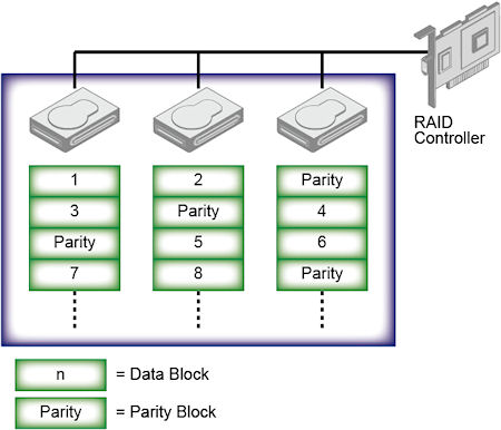
At RAID5, RAID controller distributes and writes the data to multiple disks during data recording using RAID0 method (Striping), and also parity data is calculated and saved with distribution. The specific parity disk is not decided, parity data is distributed and saved to all disks. This mechanism prevents access concentration to parity disk and performance down. Even if one disk has a failure, it can be recovered by generating the original data from other disks data and parity data. The recovery can be done just one disk failure, it’s not possible if two or more disks have failures at the same time.
The requirement for parity data is the capacity of one disk. Therefore the efficiency of disk capacity increases with number of disk. This is one of the advantage compare to RAID1 (Mirroring).
The performance of RAID5 increases when the data is read out because the reading is executed in parallel. But in write down sequence, parity data generation and reading out one data block for parity generation makes large overhead. Then the performance of writing is not so good.
Advantage of RAID5:
-
There is no specific parity disk in RAID3/RAID4 that will be bottle neck of data access.
-
More number of drives, higher performance can be expected.
-
Higher performance can be expected in case of random read sequence, different from RAID0.
Disadvantage:
-
Read is fast but write is slow, especially small number of disks. It can be recovered with big capacity cache implementation.
-
It’s not good at Software RAID system since parity calculation is required.
-
It takes long time for recovery completion.
-
It takes long time for recovery completion.
-
l The reliability when one disk has failure will be same as RAID0. (RAID6 is the a solution for this issue.)
5.2 RIO RAID5 feature
The following is the comparison of each Scan Data Disk system.
GOC6 uses full feature of RAID5, but RIO does not have the functionality redundancy. Because of the performance down, if one of the HDD was defective, the scan file save is aborted, but the scan file in HDD will be recovered. This is RIO RAID unique issue. At that time, System application software will not be up, and the attention “Call GE Service” will be displayed.
Please refer to RIO Troubleshooting guide for the procedure how to recover the Scan File.
6 Peripheral Media Tower
6.1 DVD Peripheral Media Tower
Figure 11. DVD Peripheral Media Tower (5270510-10)
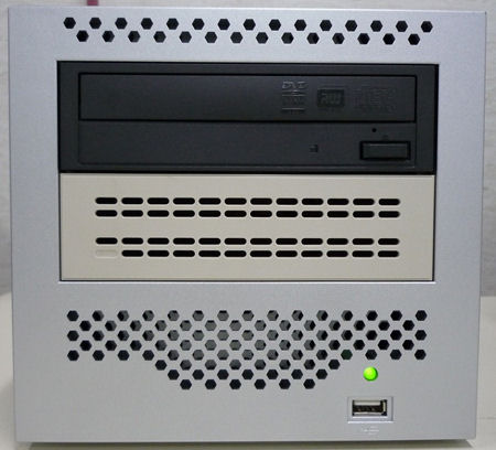
Figure 12. DVD Peripheral Media Tower (5270510-3)
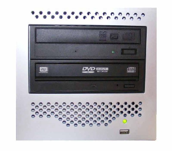
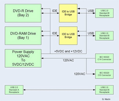
The DVD peripheral Media Tower includes one USB interface DVD-RW drive and one USB DVD-RAM drive used on the RIO Console. This Peripheral Tower is interfaced to the Host Computer using USB 2.0, instead of the SCSI Bus as on past GOCs. The following block diagram shows this interface and the IDE to USB Bridge adapters needed to connect the more commercially available DVD-R/RW and DVD-RAM Optical Drives.
Figure 13. DVD Peripheral Media Tower Block Diagram
6.1.1 DVD - R/RW Drive
The DVD-R/RW drive is an optical storage device used for data interchange (i.e. transfer of data to other systems) and for archiving data (PET only). DVD-R/RW media storage capacity is 4.7GB and is connected to the Host Computer through a USB 2.0 interface. It also supports CD-R media.
6.1.2 DVD-RAM Drive (5270510-3 Only)
The DVD-RAM drive is an optical storage device used for archiving data. DVD-RAM media storage capacity is 9.4GB and is connected to the Host Computer through a USB 2.0 interface.
6.2 -
7 Cooling System
A fan is installed in AC Box for cooling ICOM, ICOM power supply and other electronic parts in the box, located upper portion of RIO. And the cooling of Host PC is done by built-in-fans. The air flow to the Host PC fans is conducted by duct of Rear cover. Therefore the rear cover must be closed when Host PC power is on as much as possible.
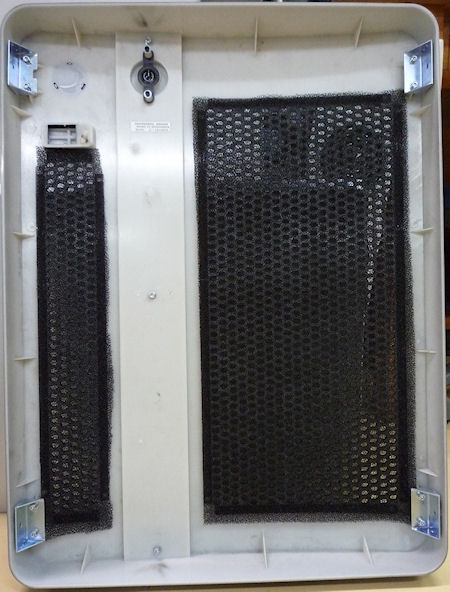
Air filter is located to both sides and front covers. Periodical cleaning is required.
Figure 14. Rear Cover
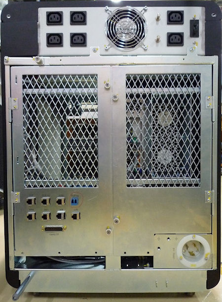
Figure 15. Air Filter
8 Service and Diagnostics
The RIO console supports two types of diagnostic, power-on test and offline test. The power-on test is a subset of offline test. This test sweeps devices condition and checks the motherboard at system power-on after OS booted. The offline test checks each device condition, interface, and environment more strictly.
RIO console supports some kind of diagnostic tools.
-
Host Computer diagnostics
-
DIP diagnostic
-
Scan Data Disk diagnostic
-
Network / connectivity test
-
GPU Diagnostics
-
Peripheral Media Tower Diagnostic
-
SCIM / Keyboard Function test
Assemblies are assigned as FRUs based on the likelihood of need for replacement and fixed-right- first-time (FRFT). The following is a breakdown of RIO Console FRUs:
-
Host Computer
-
FDIP Board
-
Hard disk drive
-
GPU card
-
Graphic card
-
Ethernet card
-
DVD ROM Drive
-
Host Power Supply
-
AC outlet box
-
Switch Hub
-
intercom
-
Peripheral Media Tower
-
Power Switch Assy
-
Fan Assy
9 Console Block Diagrams
Data Flow Dictionary
-
Gantry -> FDIP: Serial data receive from a fiber optic interface
-
FDIP -> Hard Disk: Scan Data Store
-
Hard Disk -> Recon Control: Offset Data
-
Hard Disk -> Data Restore: View Data
-
Recon Control -> IG process on host: Calibration Data, offset vector, tables, parameters
-
Data Restore -> IG process on host: view data transfer between software processes within host computer.
-
IG process -> Reconstruct images with the offset data and view data received.
-
IG process -> Image Buffer Created, and stored into image HDD (DB): Pixel image data and small header are transferred from the IG process in host or in optional IG computer to image buffer create process in Host.
Click on the PDF icon below, for a PDF version of the RIO console Interconnect Diagram.
Figure 16. RIO console Interconnect Diagram
5577708SCH.pdf