- Topic ID: concept_lzg_bkn_13b
- Version: 3.0
- Date: May 22, 2020 4:16:24 AM
Open Console (Z8G4) Theory
This module contains the following subsections:
1 Overview
The Open Console consists of the following components.
-
Host Computer - contains the System / Image Data Disks, FDIP board and two scan data disks which are Solid State Drives (SSD)
-
GPU: A graphic card is used for ASIR or Fluoro Option.
-
GSCB - GSCB shall provide all functions on SCIM and ICOM, and meet new I/O requirements.
For Open console, Host computer receives raw data from the Data Acquisition System (DAS) through an on-board Data Interface processor (FDIP) card, and stores that data in the Scan Data Disks located in the Host computer. The raw data is then delivered from the scan data disks in the Host PC to the IG processes in Host PC. The IG processes then create images. The images generated are saved in image disk in host computer.
The host computer for the Open console will be an off-the-shelf, Linux-based system.
2 Host Computer Z8G4
Host Computer in Open console is the central operation controller of the CT system.
Host Computer controls all the Open console functions and data flow, including actual image generation. Software in Host computer sends the reconstruction request, recognize the recon mode, timing, parameters, and data, and be able to generate the image set. The raw data is first restored from the disks. The Host Computer then creates an image set and requests image generation to the IG process in Host Computer. While most of the software components (e.g. Recon_Control, Data_Restore, Image_Buffer, and Data_Acq) reside on Host Computer, the components related to image generation also reside on Host Computer.
Main data flow of the Host Computer is described as follows:
-
Receive raw data from the Gantry
-
Store the raw data to the scan data disks
-
Restore the raw data from the scan data disks and transfer to buffer memory in Host Computer.
-
Take multi-image streams from Image generation processes ran on Host computer, and be saved on image disk in Host Computer.
The Host Computer is comprised of the following:
-
HP computer: a computer using a high-performance PC workstation
-
System disk: the OS and Applications software are stored on this disk
-
Image disk: Images are stored on this disk
-
Scan data SSD: the raw data are stored on 1 PCI SSD Assy (Z Turbo cards Assy) with 2 SSD modules.
-
FDIP card: the DAS Interface Processor Card
-
Gigabit Ethernet (GbE) cards
-
DVD-ROM drive: will be used for software installation and stand-alone use
-
Graphics board: connect to two LCD monitors
-
Recon GPU Card
2.1 Motherboard
The Host Computer will take advantage of a standard, off-the-shelf motherboard, using dual microprocessors to increase processing density. The Host Computer will use very high performance general-purpose processors, memory, and a server motherboard with GB Ethernet and SAS port(s), and power supply.
-
Dual Intel® Xeon® Silver 4116 2.1GHz 12 Cores Processor
-
96 GB (6x16GB) DDR4 – 2666MHz
-
Integrated with:
-
Audio
-
GBE NIC Port (eth 2 & 3)
-
USB 3.0 ports (6 rear & 4 front)
-
-
Nine (9) PCI-E expansion slots
-
SLOT 1 PCI-E: FDIP card
-
SLOT 2 PCI-E: Graphics card (Display)
-
SLOT 3 PCI-E: Not used
-
SLOT 4 PCI-E: GPU card (Recon)
-
SLOT 5 PCI-E: Not used
-
SLOT 6 PCI-E: Not used
-
SLOT 7 PCI-E: Dual Port Gigabit Ethernet card
-
-
Integrated with:
-
Audio
-
GBE NIC Port (eth 2 & 3)
-
USB 3.0 ports (6 rear & 4 front)
-
2.2 Component ID
The following picture show the Z8G4 panel and component ID.
Figure 1. Z8G4 Front Panel
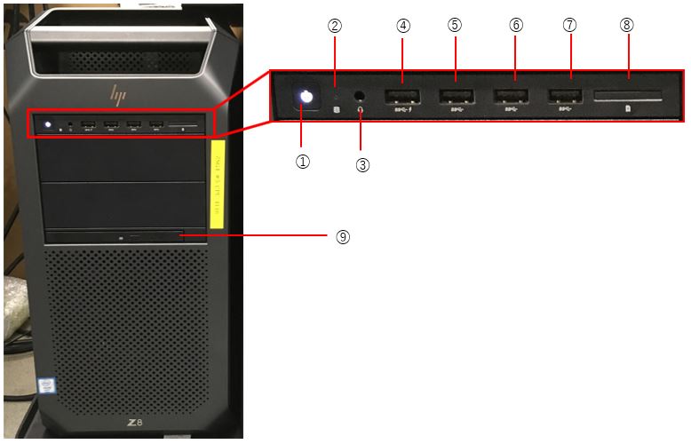
| ① | Power button |
| ② | Drive light |
| ③ | Audio-out/in combo jack |
| ④ | USB3.x SuperSpeed port with HP Sleep and Charge |
| ⑤ | USB3.x SuperSpeed port |
| ⑥ | USB3.x SuperSpeed port |
| ⑦ | USB3.x SuperSpeed port |
| ⑧ | Memory card reader |
| ⑨ | Optical Drive |
Figure 2. Z8G4 Rear Panel
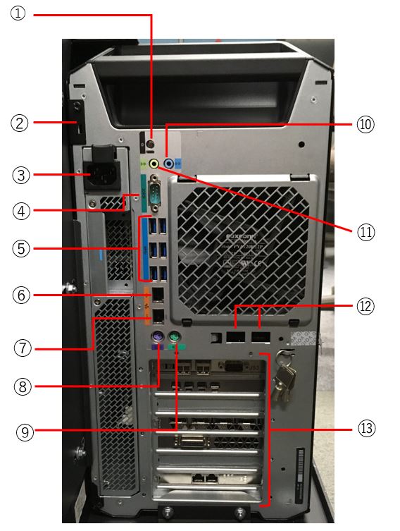
| ① | Power button |
| ② | Security cable slot |
| ③ | Power connector |
| ④ | Serial port |
| ⑤ | USB3.x SuperSpeed ports (6) |
| ⑥ | RJ-45(network) jack |
| ⑦ | RJ-45(network) jack (AMT enabled) |
| ⑧ | PS/2 keyboard jack |
| ⑨ | PS/2 mouse jack |
| ⑩ | Audio-in(microphone) jack |
| ⑪ | Audio-out(headphone) |
| ⑫ | Ethernet ports(2;select products only) |
| ⑬ | PCIe Slots(7)
|
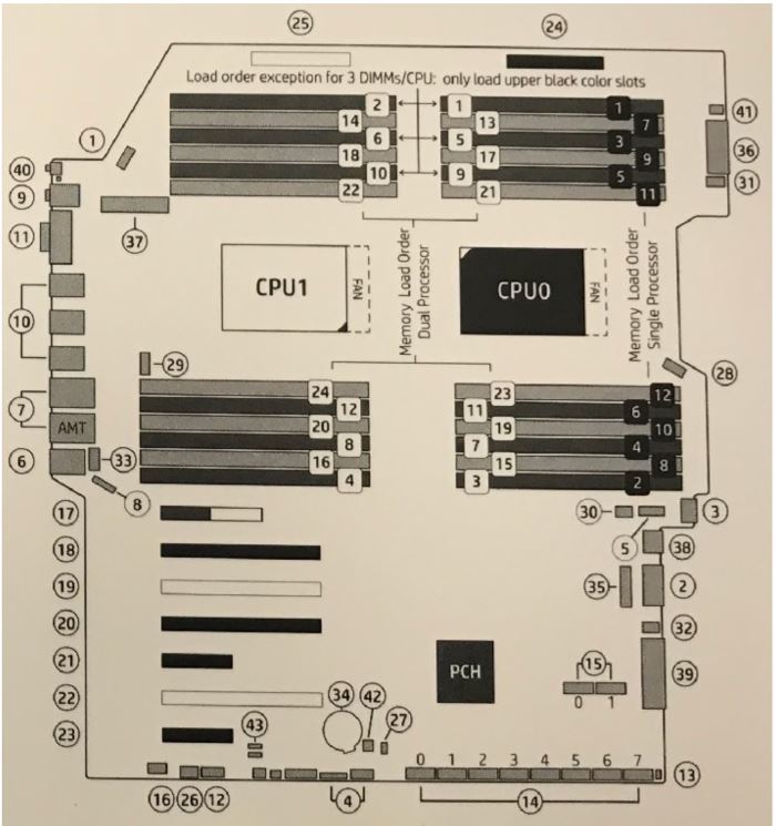
Figure 3. HP’s Z8G4 Computer Motherboard Component Layout
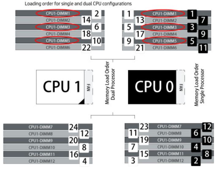
2.3 DIMM Memory Modules
The (Z8G4) computer is equipped to handle up to six (24) memory DIMM Modules in a variety of configurations. The configuration for Systems; Tri-Channel Mode 6 Slots each containing a 16GB DDR4-2666 Reg ECC RDIMM Memory Module for a total of 96 GB.
Figure 4. Z8G4 Computer Motherboard Layout - Utilization
2.4 SATA Hard Disk Drives and On-board Controller
The (Z8G4) computer utilizes two SATA hard disk drives:
-
Systems Disk: 1TB SATA 7200 RPM HDD (SATA 0)
-
Image Disk: 1TB SATA 7200 RPM HDD (SATA 1)
The System Disk (SATA Drive 0) holds the CT Operating System and Application software. The Image Disk (SATA Drive 1) utilizes one large disk partition to hold patient image data. The SATA Controller is on the Host computer motherboard and is attached to the two SATA HDDs via SATA cables. Reference Illustration 3, SATA Connectors.
-
System Disk: On-board SATA Connector Port 0 > SATA Drive Bay 0
-
Image Disk: On-board SATA Connector Port 1 > SATA Drive Bay 1
Figure 5. HP Z8G4 SATA Hard Disk Drive Bays - Internal to Z8G4
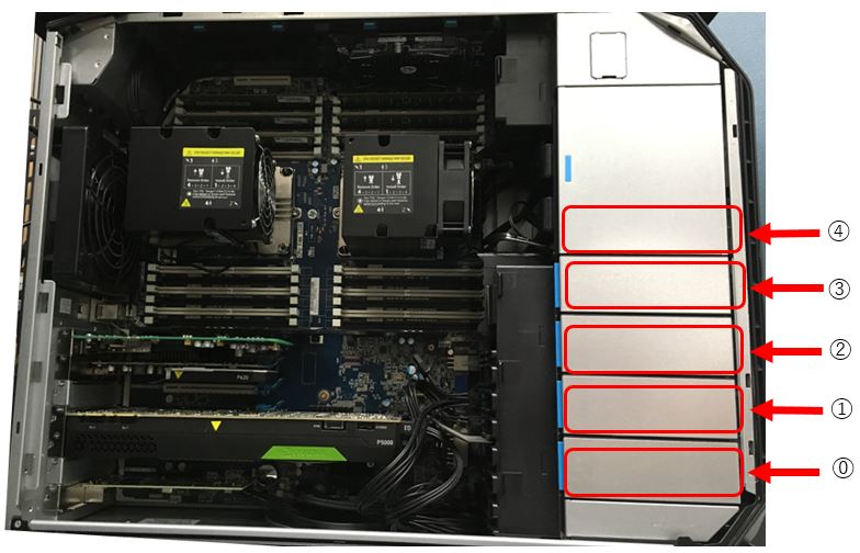
| ⓪ | System Disk |
| ① | Image Disk |
| ② | Empty |
| ③ | Empty |
| ④ | Optical Disk |
2.5 Optical Disk Drives
The (Z8G4) computer utilizes an SATA DVD Optical disk drive connected directly to the integrated SATA Controller (SATA port 6) on the motherboard. Reference Illustration 3, SATA Connectors.
-
Optical Disk Drive: On-board SATA Connector Port 6 > SATA Drive Bay 4
2.6 Dual Port GbE Ethernet Card
The Dual-Port Gigabit Ethernet HP I350 - T2 (PCIe3 x8) card, located in Slot 1 of the (Z8G4) computer motherboard, expands the Z8G4’s Ethernet interface to 4 total external ports (eth0-eth3).
2.7 GPU (Graphic Process Unit)
This PCI card accelerates the back-projection process of the Open console and is plugged into PCI-e slot in the Host Computer.
This parallel beam back-projector provides the Open console the ability to off-load the back-projection application from general-purpose processors to fully programmable hardware. This option dramatically increases the reconstruction performance per cost ratio.
Following are the high-level CTQs for the GPU card:
-
Perform parallel beam back-projection at >16fps
-
PCI-e compatible
-
Reconstruct any image matrix size up to 524,288 32bit pixels
3 Positioner Interface
3.1 Global Scan Control Box (GSCB)
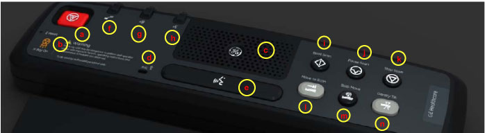
Global Scan Control Box (GSCB) together with an off-the-shelf keyboard shall be the user interface in CT system. GSCB compatible with current SCIM (Scan Control Intercom Module) and ICOM (Console Intercom Prescribed Tilt Hub). GSCB shall provide all functions on SCIM and ICOM, meet new I/O requirements (See Figure 6 for GSCB functions.)
Figure 6. Global Scan Control Box (GSCB)
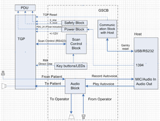
The GSCB is a component of the CT system. The following diagram shows the overall structure. The GSCB interfaced to the host PC and TGP board of the Gantry subsystem. The Host workstation is the control central of the whole CT system, The TGP is the main controller of the Table, Gantry and PDU. The GSCB is a user interface to the technician as the front end of the scan control loop. (See Figure 7.
Figure 7. GSCB Block Diagram
3.2 Prescribed Tilt
3.2.1 Overview
The Intercom block enables communication between the console operator and the patient on the table. The communication direction through the Intercom can be switched by depressing the TALK button on the keyboard. The operator can speak to the patient by depressing the TALK button (ON). When the TALK button is released (OFF) the operator can then listen to the patient.
When Auto-voice is playing, the operator can listen through the Console speaker on the Auto-voice R channel while the TALK button is released (OFF). At the same time the patient can listen through the Table speaker on the Auto-voice L channel.
If the operator depresses the TALK button (ON) while Auto-voice is playing, the Intercom will disable the Auto-voice sound and will switch the sound source to the Console microphone output. The Console microphone output is amplified and routed to the Host computer's audio input for the Auto-voice recording. The Auto voice recording will be managed by the host computer's software. It will be up to the software to start and stop recording the sound.
3.2.2 Prescribed Tilt / Reset Circuit Operation
The Prescribed Tilt circuit block will detect the status of the TILT push button in the keyboard as it is pressed or released (NO - Normal Open; NC - Normal Closed respectively) by the use of two independent paths. An invert logic signal condition (XOR) in between these two paths is used to determine the tilt condition. The pulse width of both signals shall be the same when the push button is pressed. Once the signals are received, the dual signal (redundant path) will be transmitted to the TGP board so than a single point of failure will not cause tilt motion.
The Prescribed Tilt circuit performance requirements are specified in the following:
-
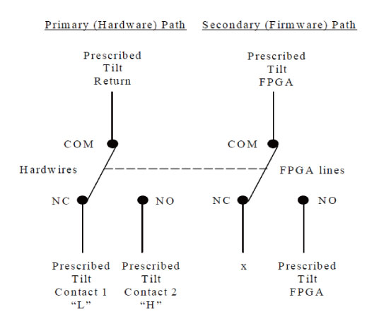
One push button switch double-pole double-throw. The button has six contacts. Contacts 1-3 are used for primary (Hardware) path. Contacts 4-6 are used for secondary (Firmware). See Figure 8.
Figure 8. Prescribed Tilt Requirements
-
The Prescribed Tilt block detects the condition of the DPDT button in the keyboard (either press or release) by using two independent paths. These two paths have an inverse logic condition between them and both signals must remain constant for the same period of time while the button is pressed.
-
No single wire can cause Tilt motion. If one of two wires fails, the circuit will not cause tilt.
-
The circuit receives dual signals and generates two independent differential signals that are sent to the TGP board. The output remains active as long as the button is pressed.
-
The defined Voltage level of the Prescribed Tilt signal is no greater than 5V.
The Reset block will receive and detect the serial break command from the Host computer serial port expander (RS-232), and then generate another pulse, which will be sent to the TGP board in the Gantry. Its performance requirements are illustrated below:
-
The Serial port expander interface sends a minimum RS-232 serial break command of 4mA and 8.1V in order to generate the Gantry Reset signal.
-
The Gantry Reset circuit responds to any pulse with a width longer than 200ms and will not respond to any pulse with a width less than 150ms.
-
Once the serial break command has been detected the output of the Gantry Reset circuit will be differential, an active high pulse signal, from 0VDC to +5VDC, with a width no less than 100ms.
4 Storage management
The scan data disks of Revolution EVO (19HW19.x or later) work with RAID1 (Software RAID).
4.1 Disk mirroring (RAID 1)
Disk mirroring, also known as RAID 1, is the replication of data to two or more disks to protect data. If one drive fails, the other one can take over and provide access to the date that's stored on that drive. Mirroring drives is good for very fast read operation, but it's slower when writing to the drives since the data needs to be written to two or more locations.
4.2 Hardware RAID vs. software RAID
Hardware RAID requires a RAID controller inside a motherboard slot that connects the drives, while software RAID uses a utility application to manage the RAID configuration.
Hardware RAID often costs more than a software option, but it can have superior performance. This approach can sometimes replace disks without shutting down the server, or hot swapping. With hardware RAID, higher write throughput speeds are supported, as well as faster recovery of lost data. Because of this, hardware RAID is the preferred option when dealing with mission-critical servers.
Software RAID is less expensive and less complex to deploy. Most operating systems include software RAID support. However, while hardware RAID has a battery backup in case of power failure, software RAID does not. Software RAID is preferred by small businesses because it offers higher performance in standard RAID levels.
5 Peripheral Media Tower
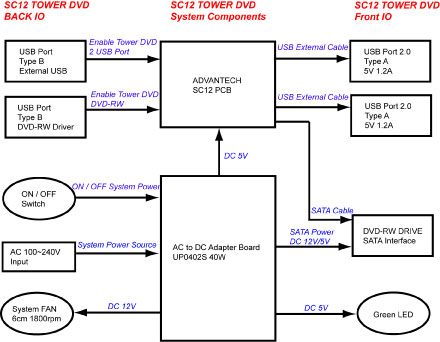
The DVD peripheral Media Tower includes one USB interface DVD-RW drive used on the Open Console. This Peripheral Tower is interfaced to the Host Computer using USB 2.0. The following block diagram shows this interface and the SATA to USB Bridge adapters needed to connect the more commercially available DVD-R/RW Optical Drives.
Figure 9. DVD Peripheral Media Tower (5270510-22)
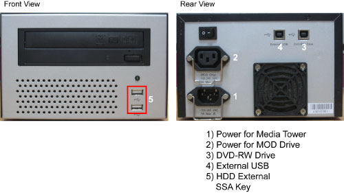
The DVD-R/RW drive is an optical storage device used for data store and data interchange (i.e. transfer of data to other systems) and for archiving data (PET only). DVD-R/RW media storage capacity is 4.7GB and is connected to the Host Computer through a USB 2.0 interface. It also supports CD-R media.
When performing Save/Restore System State, check to ensure there is no two or more USB storage devices plugged in Console/Tower at the same time which may result in incorrect data storage.
USB storage device includes SSA (Secure Service Access) key and other mobile storage devices.
Figure 10. DVD Peripheral Media Tower Block Diagram
6 Service and Diagnostics
The Open console supports two types of diagnostic, power-on test and offline test. The power-on test is a subset of offline test. This test sweeps devices condition and checks the motherboard at system power-on after OS booted. The offline test checks each device condition, interface, and environment more strictly.
Open console supports some kind of diagnostic tools.
-
Host Computer diagnostics
-
DIP diagnostic
-
Scan Data Disk diagnostic
-
Network / connectivity test
-
GPU Diagnostics
-
Peripheral Media Tower Diagnostic
-
GSCB / Keyboard Function test
Assemblies are assigned as FRUs based on the likelihood of need for replacement and fixed-right- first-time (FRFT). The following is a breakdown of Open Console FRUs:
-
Host Computer
-
FDIP Board
-
Hard disk drive (HDD) - System / Image Data Disks
-
Solid State Drive (SSD) Module - Scan Data Disk
-
Solid State Drive (SSD) Assembly - SSD baseboard
-
GPU card
-
Graphic card
-
Ethernet card
-
DVD ROM Drive
-
Host Power Supply
-
AC box
-
Switch Hub
-
GSCB
-
Peripheral Media Tower
-
Power Switch Assy
7 Console Block Diagrams
Data Flow Dictionary
-
Gantry -> FDIP: Serial data receive from a fiber optic interface
-
FDIP -> SSD: Scan Data Store
-
SSD -> Recon Control: Offset Data
-
SSD -> Data Restore: View Data
-
Recon Control -> IG process on host: Calibration Data, offset vector, tables, parameters
-
Data Restore -> IG process on host: view data transfer between software processes within host computer.
-
IG process -> Reconstruct images with the offset data and view data received.
-
IG process -> Image Buffer Created, and stored into image HDD (DB): Pixel image data and small header are transferred from the IG process in host or in optional IG computer to image buffer create process in Host.
Click on the PDF icon below, for a PDF version of the Open console Interconnect Diagram.
Figure 11. Open Console Interconnect Diagram
open console with Z8G4