- Topic ID: id_16157428
- Version: 2.0
- Date: Jun 10, 2020 2:45:57 AM
Tilt Potentiometer Assembly Replacement
Prerequisites
Overview
This procedure describes the steps to replace the Tilt Feedback Assembly. There are two different designs that a system can have. The new Tilt Feedback Assembly, Part No. 5340216, replaces the existing assembly Part No. 2356863-3/4 (found on most installed systems). The major difference between the two design is the elimination of the Tilt Enable switch from the existing design. This function is now under firmware control. This procedure includes instructions to replace both designs with the new Tilt Feedback Assembly.
1 Gantry Preparation
Procedure
- If the gantry is not at zero tilt, use the gantry control panel
to tilt the gantry close to zero tilt.note:
The tilt angle does not have to be exact. At zero tilt, there is more room for servicing the Tilt Pot Assembly.
- Move the table up to bore level and all the way back.
- Remove Right Side cover.
- Turn OFF Axial Drive, HVDC and 120 VAC switches on the Service Switch Panel.
- Perform LOTO. Refer to Equipment Service - Lockout-Tagout-PPE from Safety section.
- Remove Left Side cover.
2 Part Removal
Procedure
- Examine the tension on the Tilt Belt. The new assembly will need to be adjusted to the same tension.
- Disconnect the Tilt Enable Switch cable from the TGPU (J7).note:
Skip this step if you have a new Tilt Pot Assembly shown in Figure 2.
Figure 1. Original Tilt Pot Assembly
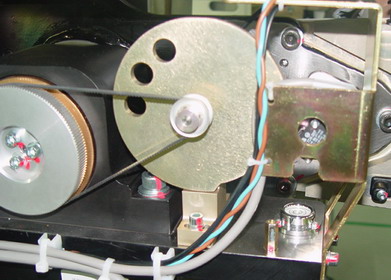
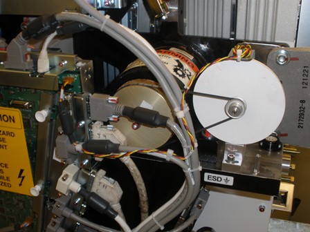
Figure 2. New Tilt Pot Assembly (5340216)
- Disconnect the Tilt Pot cable from the TGPU (J2).
- Remove the entire Tilt Pot Assembly by loosening two (2) M6 hex screws at the base of the assembly. Keep screws and washers for re-use.
3 Part Installation
Procedure
- Install new Tilt Pot Assembly using the existing two (2) M6 hex screws and washers. Do not fully tighten the screws so the belt tension can be adjusted.
- Adjust Tilt Pot Assembly position to get the same tension as
before. Placing an 8mm hex key in between the base of the Tilt Pot
Assembly and the gantry will give a good starting point.
Figure 3. Tilt Pot Assembly Installation
- Torque the two (2) M6 hex screws according to Table 7.
- Connect the Tilt Pot cable to the TGPU (J2).
- Using tie-wraps, secure the Tilt Pot cable to the gantry. Refer
to the illustrations below.
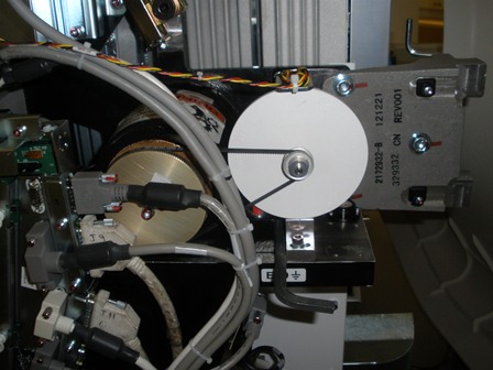
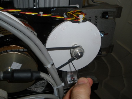
Figure 4. Installed Tilt Pot Assembly
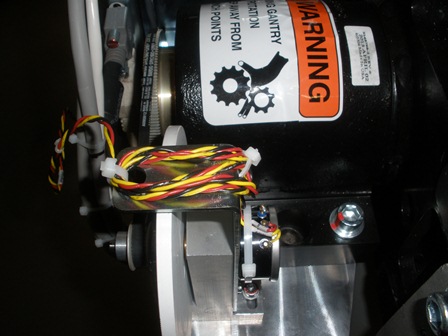
Figure 5. Tilt Pot Cable Secured
- Using a 1.5 mm hex key, loosen the two hex screws on the front
of the tilt pot pulley (do NOT remove the screws). This allows the
tilt indicator disk to freely rotate for alignment.
Figure 6. Hex Screws on Tilt Pot Pulley
4 Tilt Alignment and Characterization
Procedure
- Clear all tools from the gantry and remove LOTO.
- Using the Service Switches, turn ON 120 VAC, Service Mode and Tilt Enable.
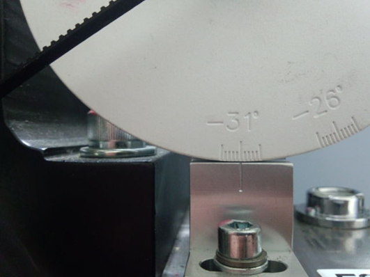
- Push down on the Tilt Service Switch to tilt the gantry backwards
(BWD) to the mechanical stops at -31O degrees.note:
The table position may inhibit tilt motion if it is in the interference matrix. Reposition the table to continue tilt.
- Rotate the Tilt Indicator Disk to -31O.
Figure 7. Alignment at -31O
- Using a 1.5 mm hex key, tighten the two hex screws on the front of the tilt pot pulley. Refer to Figure 6.
- Perform Tilt Characterization. Check for possible interference.
- Go to Service Desktop — Calibration — Mechanical Calibration — Characterize Tilt
- Follow on screen instructions.note:
When not in the Service Mode, normal tilt button function provides 0.5 degrees per button press, which is not enough resolution for proper characterization. On the Service Panel, set Service Mode (S4) switch ON to enable a fine tune adjustment of the tilt angle. Remember to turn S4 OFF when done.
note:Prior to Tilt Characterization, the tilt reading maybe greater than the 30 degrees limit. This will inhibit the tilt function from the gantry control panel. If this occurs, use the Tilt (S10) Service Switch to tilt the gantry for characterization.
- Tilt the gantry back to home position and confirm the Tilt Indicator Disk lines up at zero degrees.
- At Service Switch Panel, turn OFF Tilt Enable and Service Mode. Turn ON Axial Enable and HVDC.
- Re-install Left and Right Side covers.
5 Finalization
Procedure
- Run the System scanning test from the Functional Checks procedure list.
- Run the Quality Assurance test from the Functional Checks procedure list.
- Save System State.