- Topic ID: id_16157536
- Version: 3.0
- Date: Apr 9, 2020 8:41:59 PM
Scan Window Alignment
Prerequisites
Overview
Measure collimator and cover difference and scan window gap. Adjust as necessary. Visually inspect.
1 COLLIMATOR AND COVER DIFFERENCE
Procedure
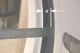
- With the front and rear covers secured in place and scan window removed, rotate the collimator to the 3 o’clock position.
- Using an appropriate (calipers or steel ruler), measure the
distance (d) in millimeters (mm) from the collimator’s surface
to the metal scan window rim, on both the front and rear covers. Record
measurements. See Figure 1.
Figure 1. Collimator Cover Gap Distance
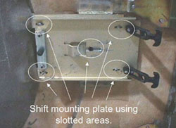
- If the difference |df-dr| between the front (f) and rear (r) measurements is greater than
3mm, the front cover must be shifted the appropriate direction. On
the front cover, lightly loosen the screws securing each mounting
plate. Slide the plates in the direction that will give you the appropriate
shift and re-secure screws. See Figure 2.
Figure 2. Gantry Cover Mounting Plate and Screws
For example, if the distance between the collimator and the front cover is 5.5mm and the distance between the collimator and rear cover is 10.5mm, then the difference is 5mm. The front cover must be shifted right at least 2mm. This means that mounting bracket on the front cover must shifted at least 2mm left.
- Repeat Step 2 andStep 3 until the difference between the two measurements is less than 3mm.
- Rotate the collimator to the 9 o’clock position.
- Repeat Step 2 through Step 4. Verify that a difference of less than 3mm is obtainable with the collimator positioned at the 9 o’clock position.
2 SCAN WINDOW GAP
Procedure
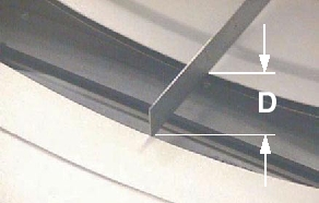
- Measure the distance (D) between front and rear covers of the
scan window rims. Measure the distance between the two covers at the
bottom of the cone. See Figure 3.
Figure 3. Scan Window Gap Distance
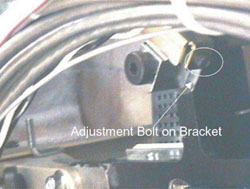
- If the spacing is the spacing is greater than 86mm for LS7.X
systems or 57mm for all other systems, bring the covers together using
the bolts located on the end of each cover latch. See Figure 4.
Figure 4. Cover Bracket Adjust Bolt Location
3 VISUAL INSPECTION
Procedure
- Install the scan window.
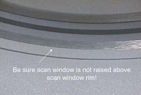
- Check that the scan window is not raised higher than the front
or rear cover at any location on the circle and that the window is
not wrinkled. See Figure 5.
Figure 5. Correct Scan Window Alignment
4 Finalization
No finalization steps.