- Topic ID: id_11038998
- Version: 3.0
- Date: Mar 5, 2020 12:15:22 PM
S-A HSDCD Slip Ring Adjustments
Prerequisites
1 HSDCD Slipring Receiver Adjustment Procedure
This document describes the steps necessary to properly replace and adjust the position of the HSDCD antenna above the emitter traces on the rotating slip ring. Accurate placement of the HSDCD antenna is important to achieve the optimal data transfer performance and to avoid contact between the ring and the stationary antenna. The optimal position of the HSDCD antenna above the emitter traces on the ring is 1.41 mm height (.060 inches), and centered. Under normal circumstances, the position of the HSDCD antenna should never need adjustment. Only adjust if there are indications of interference. Under no circumstances should the HSDCD antenna be allowed to contact the rotating components.
Procedure
 danger
- Disable power to the gantry. Lock out and Tag.
- Remove mylar window and gantry covers as required.
Refer to
- Make sure the HSDCD has no power applied - there should be no LEDs on.
- Loosen the axial adjustment screws and the radial adjustment screw for the HSDCD antenna.
- The HSDCD antenna should now be loose above the emitter. Insert the HSDCD adjustment tool between the HSDCD antenna and the emitter traces on the ring. The tool should fit snugly. The desired result is to space the HSDCD antenna above the emitter, at a height of 1.41 mm (.060 inches) above the emitter.
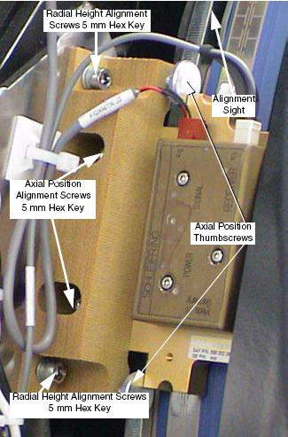
- Tighten the radial screws. Press slightly on the top of the HSDCD antenna as the adjustment screws are tightened. Reference Figure 1.
- Carefully slide the adjustment tool from between the HSDCD antenna and the emitter.
- Using the alignment sights at each end of the HSDCD antenna, center it above the center trace on the emitter PCB. Reference Figure 1.
- While holding the position of the HSDCD antenna, tighten the axial alignment screws.
- Adjust the Axial Thumbscrews to just contact the Antenna assembly. This
is the axial position preset for future reference.note:
The following illustration may not show the same power and data connection locations as your system version. Your system type may have these connections on the bottom. The adjustments shown remain the same.
Figure 1. HSDCD Receiver
- notice
- Inspect the air-gap between the HSDCD antenna and the ring as the gantry
rotates. It may be necessary to disable the gantry brake to rotate the gantry
more easily. Look for clearances between the emitter and the HSDCD antenna.
While rotating the ring, check that the emitter trace is aligned with the
HSDCD. During rotation, no parts of the HSDCD antenna should contact the emitter
surface.
-
The stationary and rotating components must never touch, even with the gantry tilted.
-
The run-out of the platter slip ring traces should not exceed 0.83 mm axially, and 0.81 mm radially.
-
Especially check clearances near the emitter solder and PCB connections.
-
The HSDCD receiver has two LEDs. One LED indicates power is applied to the HSDCD and the other indicates the HSDCD is transmitting a signal.
-
- Restore power to the system. Verify proper operation by running verification
scans. Verification procedure should consist of:
-
Observe diagnostic “DIP Stats” information. Before starting, log raw ring error count, FEC correct-able counts, and the date/time of the last file update.
-
Run 5 stationary and 50 rotational scans with x-ray. The technique is not important. It is important to exit the exam, because this triggers the “DIP Stats” update.
-
Observe diagnostic “DIP Stats” information. There should be no additional raw HSDCD ring errors or FEC correctable events.
-
- Replace the gantry covers and secure. Re-install the mylar window.
 |
2 S/A HSDCD Rotating Transmitter Power Measurements
Procedure
- Locate the HSDCD Transmitter Power supply inside the Fuse Box Assembly.
- Measure the DC voltage on the wires leading to the HSDCD Transmitter. The specification is +15 volts DC ± 2.0 volts. Use indicator LEDs to ensure proper operation.
3 S/A HSDCD Stationary Receiver Power Measurements
Procedure
- Locate the HSDCD Receiver Power supply on the rear of the right fan assembly
- Measure the DC voltage on the wires leading to the HSDCD Receiver. The
specification is +15 volts DC, ± 2.0 volts. Use indicator LEDs to ensure
proper operation.
4 Finalization
No finalization steps.