- Topic ID: id_16157535
- Version: 5.0
- Date: Sep 26, 2020 10:10:30 PM
RTP Alignment Test Procedure
Prerequisites
Figure 1. Tools for Table Alignment
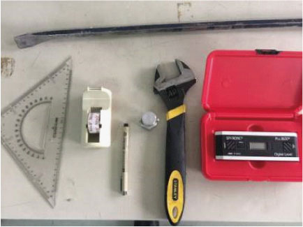
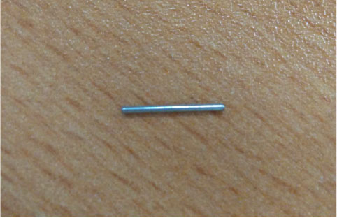
Figure 2. Paper Clip (Staple Pins)
Overview
RTP (Radiotherapy Treatment Planning) provide the ACCOMPANYING DOCUMENTS to describe the procedures for aligning the top of the PATIENT SUPPORT with respect to the TOMOGRAPHIC PLANE.
1 Preparation
NOTE: Before make RTP alignment, it required the system mechanical alignment well, and alignment light is in good condition, otherwise, please go to adjust alignment light.
Procedure
- Set a RTP Flat top on cradle.
- Install a lock bar on FTT (Flat Table Top).
- Move cradle to adjust FTT (Flat Table Top) to ISO center plane.
- Prepare two steel pins (diameter<1mm) and stick at the front and end cross labels.
2 General Information
2.1 RTP Overview
Procedure
- notice
- Skew
IEC60601-2-44:2012 Clause 201.101.2.3a Requirements: The alignment procedure shall require the axis of the horizontal movement of the top of the PATIENT SUPPORT to be perpendicular to the x-axis of the TOMOGRAPHIC PLANE within ± 1º.
- Shifting
IEC60601-2-44: 2012 Clause 201.101.2.3b Requirements: The alignment procedure shall require the centerline of the top of the PATIENT SUPPORT to be marked at the front end (M1) and at a distance of 1 m from the front end (M2). The difference between the centerline and the z-axis indicated by the sagittal light marker shall be measured at the position of the scan plane for both M1 and M2. Neither d1 nor d2 shall exceed 2 mm (see Figure 201.104). If the sagittal light marker does not extend to the scan plane, the measurement shall be taken at the external light marker position.
- Tilt
IEC60601-2-44: 2012 Clause 201.101.2.2 Requirements: The alignment procedure shall require the accuracy of the alignment to be ±0.5º or less with respect to the horizontal plane. The alignment procedure shall require this measurement to be taken on the retracted top of the PATIENT SUPPORT, without load, after installation.
- ISO Height
 |
2.2 Set-up Specification
Procedure
- Set Gantry at 0 degree.
- Turn ON the laser alignment lights on the gantry display control
panel, adjust the table height until the top surface of FTT (Flat
Table Top) reaches ISO center.
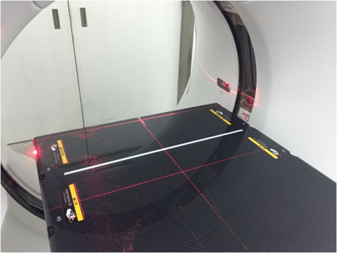
Figure 3. Table Height on ISO Center
3 Alignment Procedure of the patient support in the Horizontal Plane_Skew
3.1 Scan and Measure
Procedure
- Perform scout scan at the locking bar.
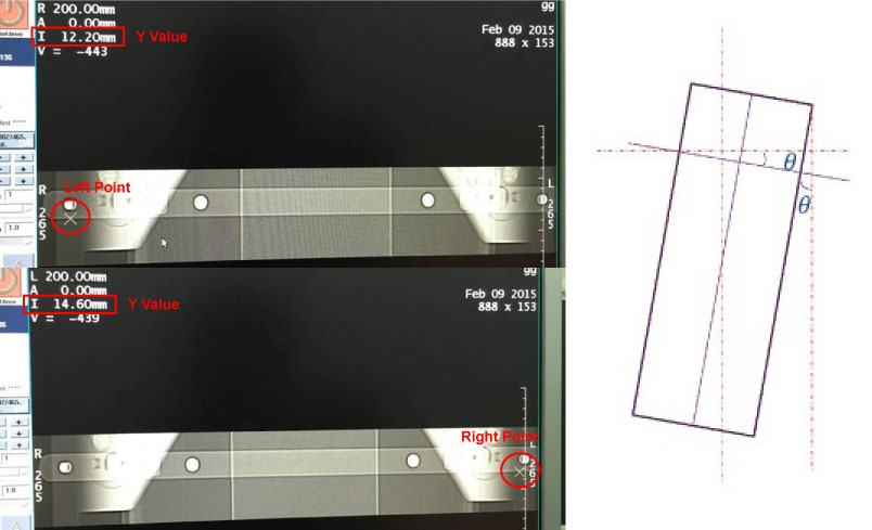
- Choose two points (±200mm@x-axis) on locking bar of image,
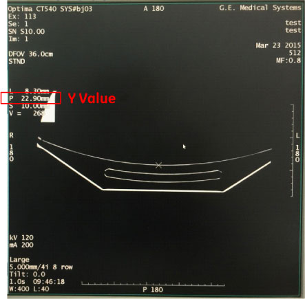
and record Y value of two points.note:
The recommended taking point method is to gather two points along the edge of the locking bar to ensure keeping a straight line.
Figure 4. Take Points on Locking Bar
- Select Service Desktop
- Click the RTP Alignment Tool under the Calibration
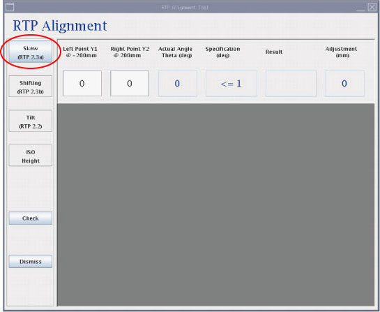
- Click on Skew (RTP 2.3a) button.
- Input Y value of two points into textbox and the result and
suggested adjustment will come out.
Figure 5. RTP Alignment Skew
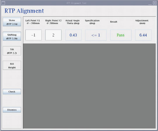
- If the result is passed, the next step will be enabled.
Figure 6. RTP Alignment Skew (Pass)
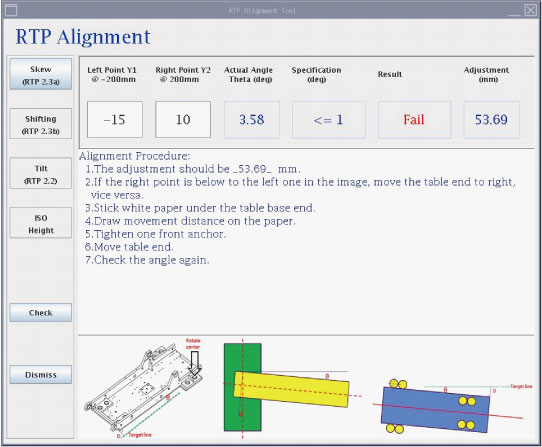
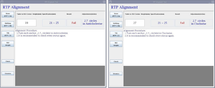
- If it is failed, the alignment procedure will be provided.
Figure 7. RTP Alignment Skew (Fail)
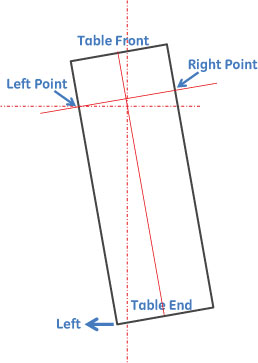
3.2 Adjustment Direction
Procedure
- When the Right Point is below to the Left Point, move Table
End to Right.
Figure 8. Adjustment Direction
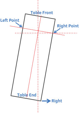
- When the Right Point is above to the Left Point, move Table
End to Left.
Figure 9. Adjustment Direction
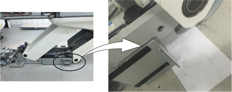
3.3 Table Adjustment
Procedure
- Stick white paper on the ground by ruler alignment at the end.
- Draw movement distance on the paper.
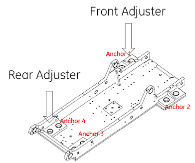
- Tighten up one front anchor.
- Table movement with crowbar.
- Scan and measure the angle again.
Figure 10. Scan and Measure Angle
4 Alignment Procedure of the patient support in the Horizontal Plane_Shifting
4.1 Scan and Measure
Procedure
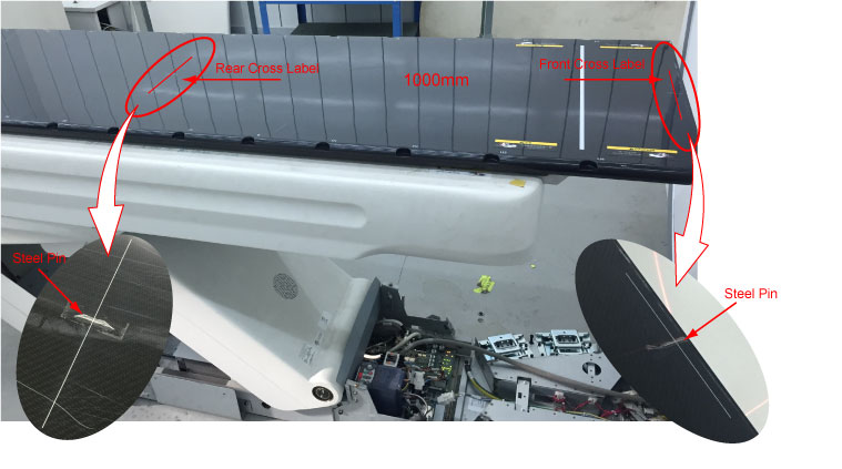
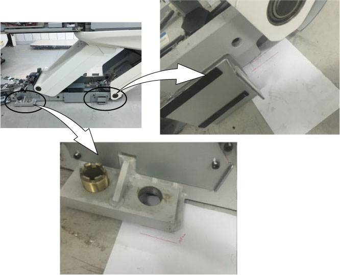
- Attach Steel Pins (or Paper Clip) at the FTT (Flat Table Top)
front and back cross labels (1000 mm).
Figure 11. Steel Pins Attaching
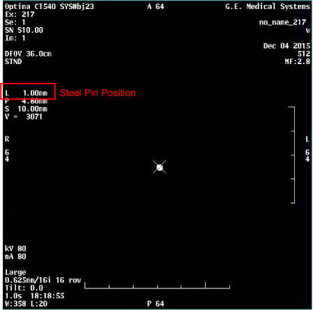
- Axial scan on both steel pins and record distances.
Use measure tool to select the center of steel pin and record distance values.
Figure 12. Scan Steel Pins
- Click on Shifting (RTP 2.3b) button.
Figure 13. RTP Alignment Shifting
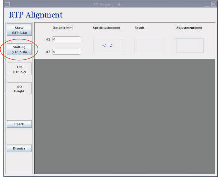
- Input two distances (distance value shown in Figure 12) into textbox and the result and suggested adjustment will come out.
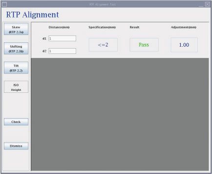
- If the result is passed, the next step will be enabled.
Figure 14. RTP Alignment Shifting (Pass)
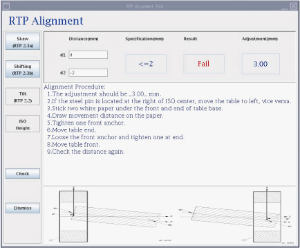
- If it is failed, the alignment procedure will be provided.
Figure 15. RTP Alignment Shifting (Fail)
4.2 Adjustment Direction
Procedure
- When the image center of steel pin is located at the Left of the ISO center, the table should be move to Right.
- When the image center of steel pin is located at the Right of the ISO center, the table should be move to Left.
4.3 Table Adjustment
Procedure
- Stick white paper on the ground by ruler alignment at the front and end.
- Draw movement distance on the paper.
- Tighten up one anchor.
- Table movement with crowbar
- Tighten up another anchor
- Table movement with crowbar again
- Scan and measure the distance again
Figure 16. Scan and Measure
5 Alignment Procedure of the patient support in the Vertical Plane -Tilt
5.1 Measure
Procedure
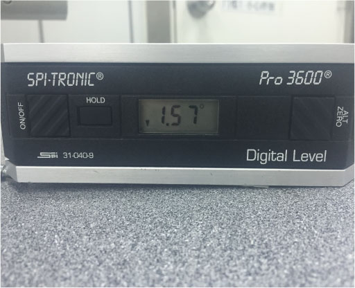
- Measure FTT (Flat Table Top) tilt by using angle gauge (Model:
SPI-PRO3600) to test 4 positions on FTT (Flat Table Top).
Figure 17. Measure FTT Tilt
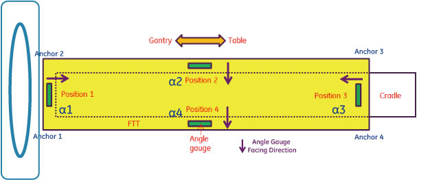
- Record angles of FTT as α1, α2, α3 and α4
- The α1, α2, α3 and α4 are the angle parallel to the edge
- α2 and α4 are the table tilt angles required in clause 201.101.2.2. Both α2 and α4 need to be ± 0.5º or less
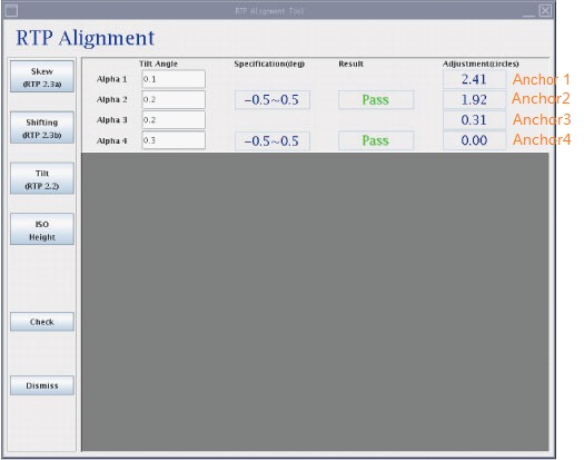
- Click on Tilt (RTP 2.2) button.
- Input four angle into textbox and the result and suggested adjustment
will come out.note:
Please input negative or positive in Tilt Angle of Alpha 1~4 according to Angle Gauge display result (See Angle Gauge Display).
- If only two results are passed at the same time, the next step
(ISO Height) will be enabled.
Figure 18. RTP Alignment Tilt (Pass)
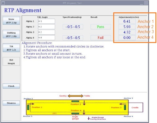
- If any result is failed, the alignment procedure should be executed.
Please adjust anchor adjuster according to the screen displays value
(as shown below red box)note:
If any of Alpha2 and Alpha4 is out of specification and failed, FE needs to adjust all of anchors as shown software alignment tool display.
Figure 19. RTP Alignment Tilt (Fail)
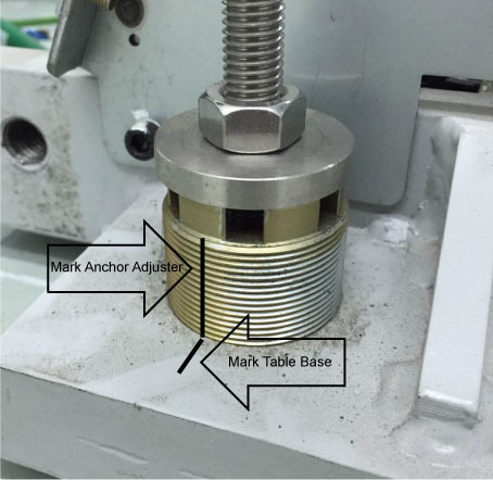
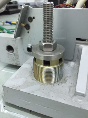
Using a marking pen, mark the current position of the anchor leveling adjuster and table base. This will provide a starting point for determining the turns made of the adjuster. See Illustration below.
Example: For integer, one full turn will return the adjuster marking in-line with the table base marking. For decimals, approximately estimate the corresponding turns.
Figure 20. Marking Starting Point for Adjustment
5.2 Angle Gauge Display
Procedure
- The left side is higher than the right side, the angle gauge
displays arrowdown (negative).
Figure 21. Angle Gauge
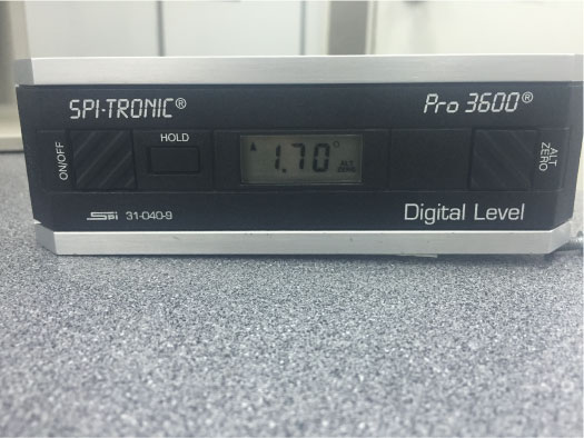
- The left side is lower than the right side, the angle gauge
displays arrowup (positive).
Figure 22. Angle Gauge
5.3 Adjustment
Procedure
- At the very beginning, four anchor leveling adjusters should
be loaded by attempting to turn it.
Figure 23. Table Anchor
- Anchor adjustment should be done one by one at small amount.
- After adjustment all finished, there might be some anchor leveling
adjuster loose. In this case, tighten it by hand to confirm it is
loaded.
Figure 24. Anchor Adjustment
- Repeat the above measure procedures to ensure two results are pass.
6 ISO Height
After adjusting 4 anchors, table height should be within ISO- 21mm~ISO-25mm according to system installation manual (EE).
6.1 Scan and Measure
Procedure
- Lift table to the highest position.
- Axial scan on steel pin.
- Find out the lowest point of cradle and record the vertical
value.
Figure 25. Scan Steel Pins
- Click ISO Height button.
Figure 26. RTP Alignment ISO Height (Pass)
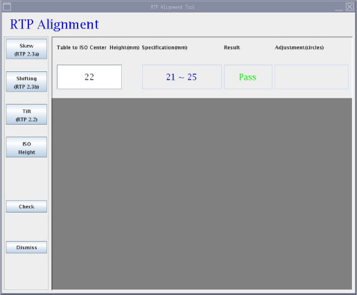
Figure 27. RTP Alignment ISO Height (Fail)
- Input the vertical value into textbox and the result and suggested adjustment will come out.
- If the result is passed, RTP Alignment is finished.
- If it is failed, the alignment procedure will be provided.
6.2 Adjustment
Procedure
- At the very beginning, four anchor leveling adjusters should be loaded by attempting to turn it.
- Turn each anchors shown as Anchor adjustment should be done one by one at small amount.
- After adjustment all finished, there might be some anchor leveling adjuster loose. In this case, tighten it by hand to confirm it is loaded.
- If any table alignment is taken, it may affect the other status. It is recommended to check the status again till four steps are passed together.
7 Finalization
No finalization steps.