- Topic ID: id_15460446
- Version: 5.0
- Date: Jan 20, 2020 8:34:48 PM
Plenum Fan, Fan Plate Assembly Replacement
Prerequisites
Overview
This procedure defines the information necessary to properly remove and replace a fan or fan plate assembly. Individual fans may or may not be spare part.
1 Procedure Steps
Procedure
- Remove the Gantry Right side cover.
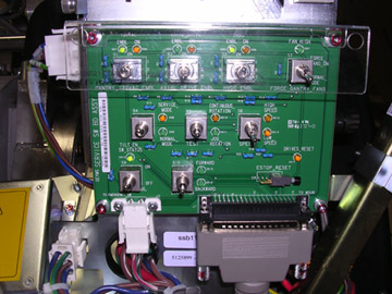
 danger
- Disable Axial Drive and HVDC service switches on the service
switch panel.
Figure 1. Service Switch Panel
- Position the DAS/Detector at 12 o’clock and lock gantry rotation.
- Shut down power to the rotating assembly using the Service Switch panel 120 VAC service switch. See Figure 1.
- Remove gantry left side, top and front covers.
Refer to
2 Removal
Procedure
- Disconnect the fan control cable from the fan plate and loosen
captive screws holding the fan plate to the Air plenum. See Figure 2 for Plenum front view.
Figure 2. Detector Plenum
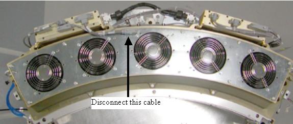
- Lift off the fan plate. The entire plate or individual fan can now be replaced.
3 Installation
Procedure
- If replacing a single fan, Install new fan onto the plate and
torque nuts to:
- Install the fan plate assembly. There are guide pins on each
end of the plenum casting.note:
Be careful not to pinch wires or harnesses between the fan plate and the air plenum casting.
- Torque fan plate screws to:
- Reconnect fan control cable.
- Turn on the 120 VAC service switch at the service switch panel. Check to make sure all 5 fans are running. Use a piece of paper or similar object to make sure fans are pulling air into the plenum. A fan that is not running will still have the fan blades moving as air is pushed back out of the plenum through that fan port.
- Turn off the 120 VAC service switch, release the gantry rotational
lock and install gantry covers, all except the right side cover.
Refer to
- Turn on the 120 VAC, HVDC and Axial drive service switches.
- Install gantry right side cover.
4 Finalization
Procedure
- If any calibrations were run with a fan not working (Fastcal or Detailed Calibration), those calibrations will need to be run after repair is complete.
- Perform the Quality Assurance Test.
- Perform a Save State operation if Detailed Calibrations were performed.