- Topic ID: id_16158074
- Version: 3.0
- Date: Nov 27, 2020 2:16:53 AM
PDAS ADB Board Replacement
Prerequisites
Overview
Replace suspected faulty board and verify proper operation and Image Quality:
-
Remove covers.
-
Access ADB Boards.
-
Replace part.
-
Verify operation.
-
Assemble gantry.
1 ADB Removal
Procedure
- Position the Table to its lowest position.
- Remove the Gantry right side cover.
- notice
- Turn OFF Axial Enable, HVDC, and 120VAC switches on the Service Switch panel.
- Remove the rest of the gantry covers.
- Position the PDAS at the 2 o'clock position
- Lock the Gantry in position, using the rotational lock.
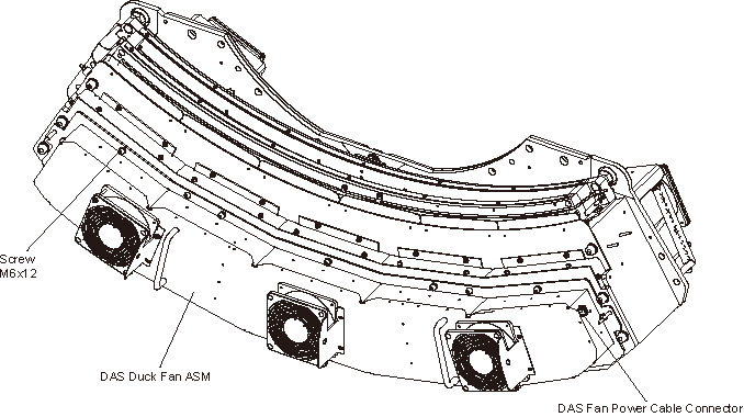
- Disconnect the fan power cable from the Duct Fan Cover.
- Remove the Duct Fan Cover by unscrewing its M6x12 allen screws
by a
 on the Duct Fan Cover.
Figure 1. Remove the Duct Fan ASM
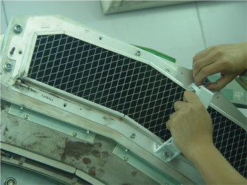
- Install two the cover handles (5488043) shipped with system
ship collector on the Air Filter ASM.
Figure 2. Install the Cover Handles
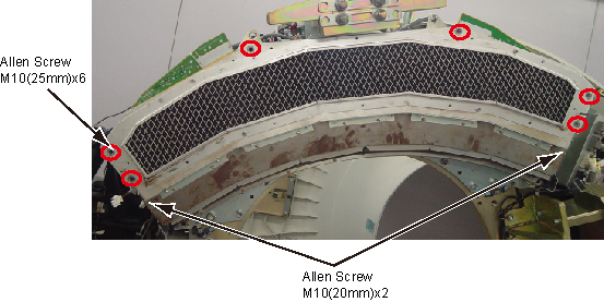
- Remove the Air Filter ASM and Detector Duct Fan Cover together
by unscrewing their M10x8 allen screws.
Figure 3. Remove Air Filter ASM and Detector Duct Fan Cover
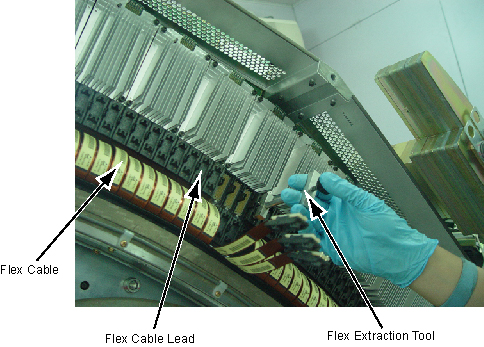
- Put on Nitrile protective gloves and wrist strap and use ESD precautions.
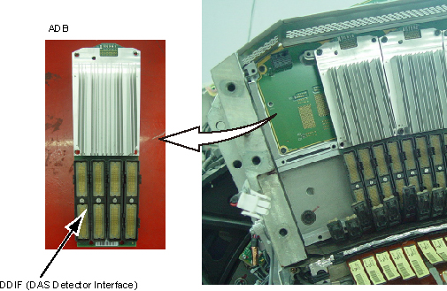
- Pull out the Flex Cable Leads from the DDIFs of the defective
ADB with the Flex Extraction Tool.
Figure 4. Remove the Flex Cable
- Remove the defective ADB by unscrewing its M4x6 screws.
Figure 5. Remove the ADB
- Remove DDIF slot and Install it to new ADB, refer to DAS Interposer Replacement. If the swap ADB position, skip this step.
- Place the defective ADB into an ESD bag.
 |
2 ADB Installation
Procedure
- Take out the new ADB from ESD bag.
- Align the ADB location hole to pin on the backplane and push ADB in place.
- notice
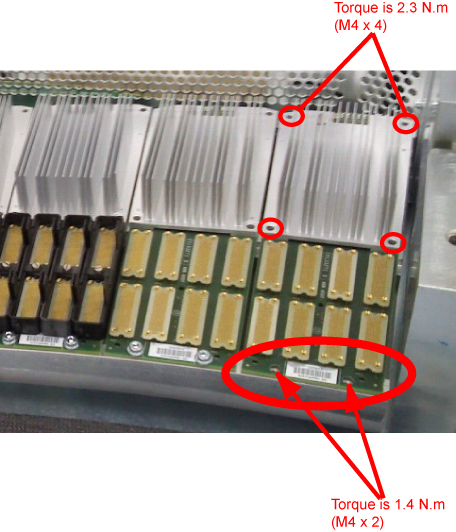
- Push the ADB toward the backplane, and secure the ADB in place
by screwing its 6 screws. Screws torque refer to below illustration:
- Reconnect the Flex Cables to the new ADB.
Make sure the Flex Cable Leads are pushed perpendicularly in the DDIFs of the ADB.
- Reinstall the Air Filter ASM and Detector Duct Fan Cover by screwing their 8 allen screws. (Torque: 38.4 N.m)
- Uninstall two the cover handles from the Air Filter ASM.
- Reinstall the Duct Fan Cover by screwing its 12 allen screws. (Torque: 7.9 N.m)
- Reconnect the fan power cable to the Duct Fan Cover.
- Disengage the rotational lock.
- Turn ON Axial Enable, HVDC, and 120VAC switches on the Service Switch panel.
|
3 Finalization
Procedure
- Perform a DAS Rest from the Reset Menu.
- Depending on the fault, let the board warm-up five (5) minutes to verify it fixed the problem, but at least 1 hour before DAS Tools, FastCal, or Image Quality scans. A cold board may fail Offset Drift or Pop Noise until it is in normal operating temperature ranges.
- Verify proper functionality:
- Run at least 10 passes of Scan Data Path Diagnostic.
- Run 1 pass of DAS Tools.
- Run FastCal, if only one card replaced.
- Run full FastCal and Phantom Cal, if more than 2 cards replaced
or if I/Q fails due to replaced boards.
Upon running FastCal the first time, Daily IQ check may fail, and can generally be ignored, provided the images look good.
- Take 10 I/Q scans of the 48cm phantom.
- Verify fault or reason to replace the board now passes.
- Perform Saving System State
- Reassemble the Gantry covers.