- Topic ID: id_16157868
- Version: 2.0
- Date: Jun 10, 2020 2:46:21 AM
IMS Cable Bear Assembly Replacement
Prerequisites
Overview
This procedure is for the Global PET/CT Table, with fixed position IMS and GT1700V Table
Procedure
- Raise the Table to maximum height.
- Move the Cradle to OUT limit position.
- Remove power from Table by turning off 120VAC, Axial Drive and HVDC switches on Service Switch Panel.
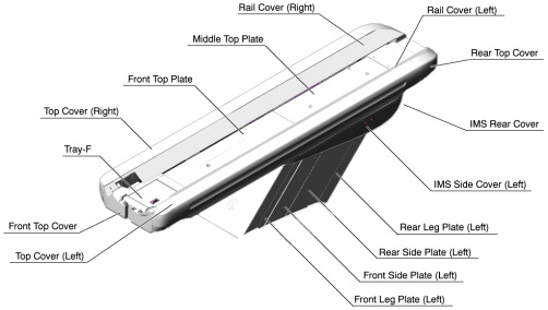
- Remove the following Table Covers:
-
Top Cover (Right/Left)
-
Front Top Cover
-
Rail Cover (Right/Left)
-
Rear Top Plate
-
IMS Rear Cover
-
IMS Side Cover (Right/Left)
-
Liner Scale Cover
Figure 1. Table Covers
-
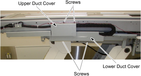
- Remove two screws holding the upper duct cover, and remove the cable duct cover from the Table.
- Remove two screws holding the lower duct cover, and remove the
cable duct cover from the Table.
Figure 2. Cable Duct Cover Removal
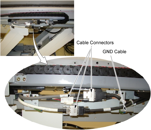
- Disconnect three cable connectors and a GND wire on the cable
duct, and remove any clamps.
Figure 3. Cable Connection of Cable Duct
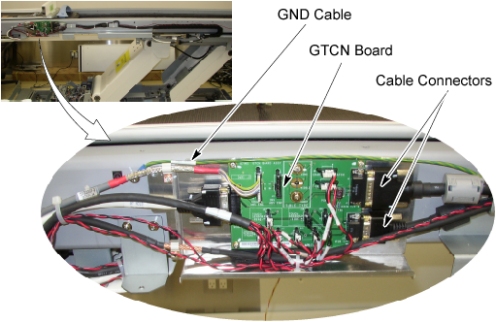
- Disconnect two cable connectors and a GND wire from the GTCN
board, and remove any clamps.
Figure 4. Cable Connection of GTCN
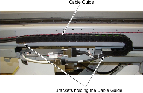
- Remove two support brackets (holding the IMS cable guide to
the IMS frame) by unscrewing 2 (x2) screws.
Figure 5. Support Bracket Removal
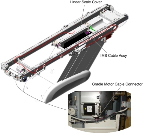
- Cut any tie-wraps holding the IMS cable to the Table frame,
and remove any clamps, then disconnect the cradle motor cable connector.
Figure 6. IMS Cable Assy Routing
- Remove the IMS cable bear assembly from the Table.
- Install the new IMS Cable Bear Assy by referring to Step 11through Step 7.
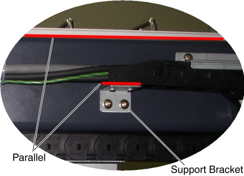
- Verify that the top surface of the support bracket is parallel
with the top surface of the Table frame.
Figure 7. Support Bracket Configuration
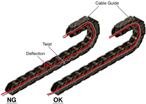
- Verify that the cables in the cable guide have no deflection
and are not twisted.
Figure 8. Cable Configuration in the cable guide
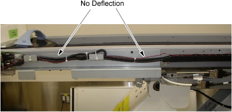
- Verify that the cables on the Table frame have no deflection.
Figure 9. Cable Configuration on the Table Frame
Finalization
- Re-install the touch sensor assy R, all removed Table trays and covers.
- Power up the Table from the Service Switch Panel.
- Verify that the IMS moves IN and OUT normally.