- Topic ID: id_16157886
- Version: 5.0
- Date: May 13, 2022 1:41:34 AM
Hydraulic Cylinder Replacement
Prerequisites
Overview
Procedure
- Raise the Table to maximum height.
- Perform this step if applicable:
(For Global PET/CT Table, with fixed position IMS) Move the Cradle to OUT limit position.
(For Global PET/CT Table) Move the Cradle and IMS to OUT limit position.
(For GT1700 and GT2000 Table) Move the Cradle and IMS to OUT limit position.
(For GT1700V) Move the Cradle to OUT limit position.
- Remove power from Table by turning off 120VAC, Axial Drive and HVDC switches on Service Switch Panel.
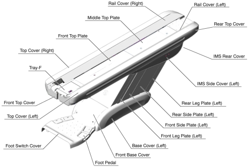
- Remove the following Table covers:
-
IMS Rear Cover
-
IMS Side Cover (Right/Left)
-
Front/Rear Side Plate (Right/Left)
-
Front/Rear Leg Plate (Right/Left)
-
Base Cover (Right/Left)
-
Front Base Cover
Figure 1. Table Covers
-
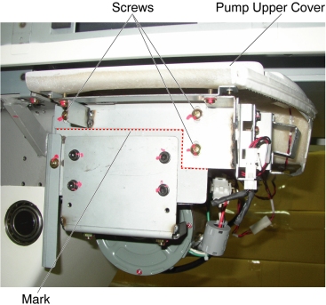
- Remove the Pump Upper Cover as follows: (For GT1700V:
Skip this step)
- Mark the position of pump upper cover on both sides for re-installation.
- Disconnect the cable connectors of the tape switches and touch sensors.
- Remove six (6) screws holding the both sides of the pump upper
cover, and remove the pump upper cover.
Figure 2. Pump Upper Cover Removal
- Attach the Table Support Tool as follows:
- Perform this step if applicable:
(For GT1700 and GT2000 Table) Skip this step.
(For GT170V Table) Skip this step.
(For Global PET/CT Table and Global PET/CT Table with fixed position IMS) Release Transporter and manually push up against the rear Hard Stop.
Figure 3. Table Pushed Against Hard Stop (Global PET/CT Table)
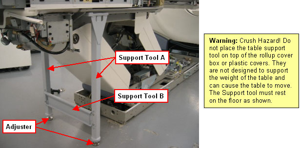
 warning
- Perform this step if applicable:
(For GT1700 and GT2000 Table) Skip this step.
(For GT1700V Table) Skip this step.
(For Global PET/CT Table and Global PET/CT Table, with fixed position IMS) Attach one of the “L” shaped alignment blocks to the front linear rail (The alignment blocks and hardware came with the Table and should have been stored away during install). Tighten bolt as shown in order to secure the Transporter.
Figure 4. Tighten Alignment Block (Global PET/CT Table)
- The adjuster of the support tool A should be partially extended,
about 3 cm, before supporting the Table.
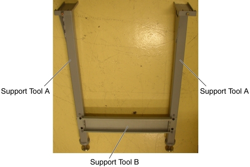
Figure 5. Table Support Tool
- Attach the support tool A to the left top frame, and turn the
set (hexagon) screw to CCW to fix the support tool A.
Figure 6. Support Tool 'A' Attachment (GT1700, GT2000, Global PET/CT Table and GT1700V)
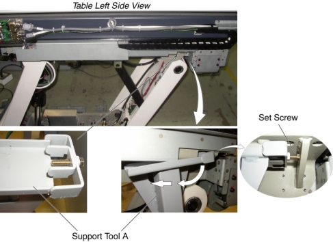
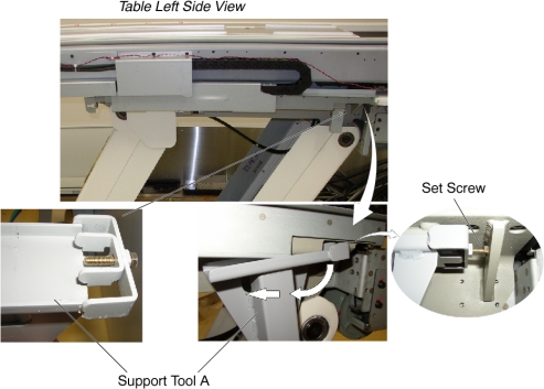
Figure 7. Support Tool 'A' Attachment (Global PET/CT Table, with fixed position IMS)
- Attach the other support tool A to the right top frame, and turn the set (hexagon) screw to CCW to fix the support tool A.
- Attach the support tool B to the support tool A using 4 screws.
- Power up the Table from the Service Switch Panel.
- Extend the adjusters by turning them so that the adjusters touch
the floor, and lower the Table onto the support. Make sure that there
is no oil on the floor and the support tool is installed perpendicular
to the floor.
Figure 8. Table Support Tool Attachment (GT1700, GT2000 and GT1700V Table)
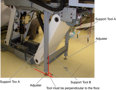
Figure 9. Table Support Tool Attachment (Global PET/CT Table and Global PET/CT Table, with fixed position IMS)

- Perform this step if applicable:
- notice
- Remove power from Table by turning off 120VAC, Axial Drive and HVDC switches on Service Switch Panel.
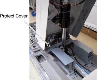
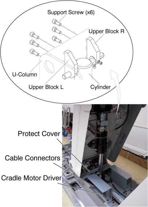
- Remove the protect cover by unscrewing 2 screws.
Figure 10. Protect Cover
- Perform this step if applicable:
(For Global PET/CT Table, with fixed position IMS) Disconnect the cable connectors from the Cradle Motor Driver.
(For Global PET/CT Table) Disconnect the cable connectors from the Cradle/IMS Motor Driver.
(For GT1700 and GT2000 Table) Disconnect the cable connectors from the Cradle/IMS Motor Driver.
(For GT1700V Table) Disconnect the cable connectors from the Cradle Motor Driver.
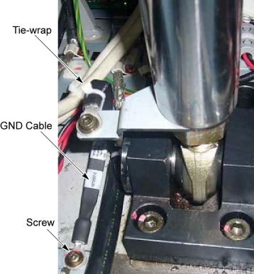
- Cut any tie-wraps holding the valve cables and hoses to the Table frame.
- Disconnect the valve cable connector.
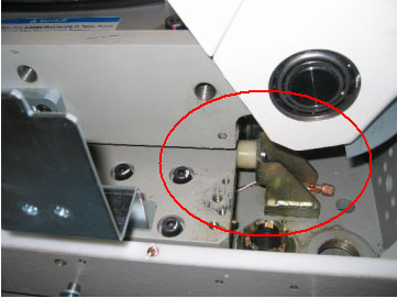
- Unscrew one screw, and remove the cylinder GND cable from the
Table.
Figure 11. Cylinder GND Cable
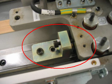
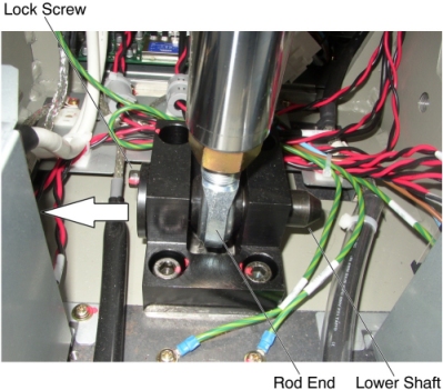
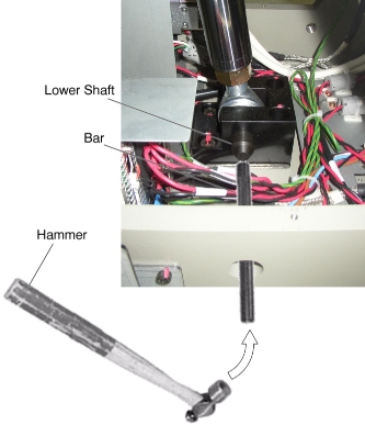
- Remove the lower shaft as follows:
- Unscrew a lock screw.
- Draw out the lower shaft from the rod end.
Figure 12. Lower Shaft Removal
 note:
note:If the lower shaft is hard to draw out, hammer the opposite side of the lower shaft.
Figure 13. Lower Shaft Removal with Hammer
- Disengage the upper block R and upper block L from the U-column
by unscrewing 6 support bolts.
Figure 14. Upper Blocks Removal (GT1700, GT2000, Global PET/CT Table and GT1700V)
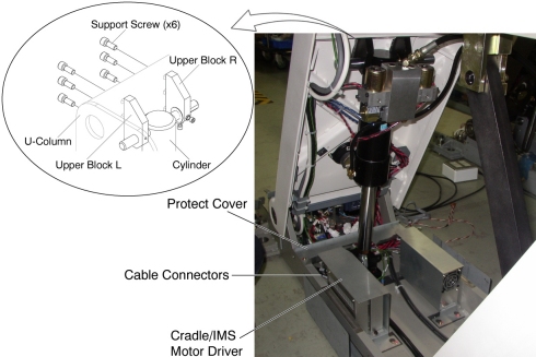
Figure 15. Upper Blocks Removal (Global PET/CT Table, with fixed position IMS)
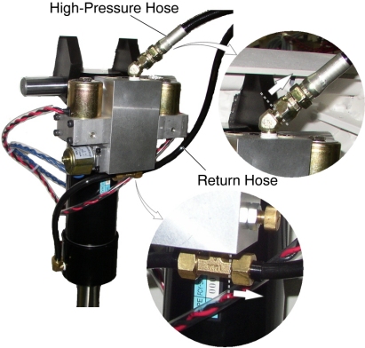
- Remove the Cylinder with hoses from the Table, and put it to the oil-pan.
- Disconnect the high-pressure hose from the cylinder (a oil may spill out from the hose), and connect it to the new cylinder.
- Disconnect the return hose from the cylinder (a oil may spill
out from the hose), and connect it to the new cylinder.
Figure 16. High-Pressure Hose and Return Hose
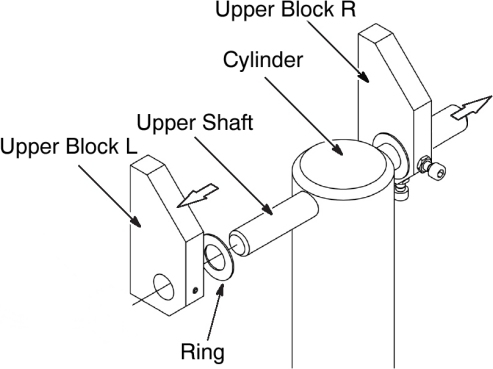
- Remove the upper shaft from the cylinder as follows:
- Loosen 2 set screws on the stopper L, and remove the stopper L, upper block L and a ring from the upper shaft.
- Draw out the upper shaft with the upper block R from the cylinder.
Figure 17. Upper Shaft Removal
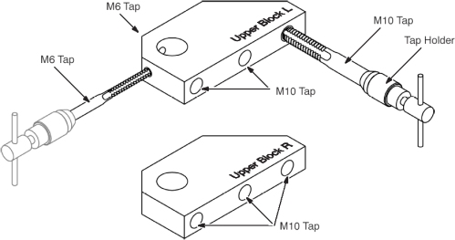
- Perform re–tapping to screw holes of the upper blocks using
the tapping tools provided in the Table cylinder replacement tool.
Figure 18. Re-tapping the Upper Blocks (L/R)
- Insert the upper shaft (upper block R and the ring) cross the hole of the new cylinder.
- Position the rod end of the new cylinder into place, and insert the lower shaft, then tighten the lock screw.
- Connect the valve cable connectors.
- Align the screw holes of the upper blocks and U-Column as follows:
- Power up the Table from the Service Switch Panel.
- Adjust the length of the cylinder using Table Up/Down switch.note:
If the cylinder is retracted, push the cylinder down pressing the Table down switch.
- Engage the upper blocks to the U-Column using the 6 bolts with Loctite (Torque: 55N.m).
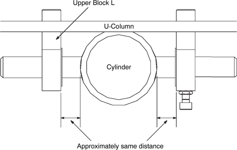
- Verify that the position of the cylinder is the following.
Figure 19. Position of the Cylinder
- Connect new cylinder GND cable using one screw as shown in Figure 11.
- Raise the Table to its highest position, and verify that the
upper blocks are securely installed.note:
If the Table can not be raised to the highest position due to a lack of oil, pour oil into the pump (refer to Step 32).
- Perform this step if applicable:
(For Global PET/CT Table, with fixed position IMS) Re-install the protect cover.
(For Global PET/CT Table) Install new protect cover included in the replacement kit.
(For GT1700 and GT2000 Table) Install new protect cover included in the replacement kit.
(For GT1700V Table) Re-install the protect cover.
Figure 20. Protect Cover
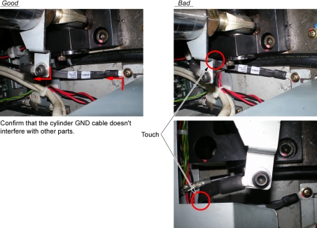
- Verify that the cylinder GND cable does not interfere with the
protect cover (see Figure 21).
Figure 21. Cylinder GND Cable and Protect Cover
- Carefully remove the Table support tool.
- Verify that all cabling and hosing are in the proper configuration and will not catch, then tie-wrap the cables and hoses in place.
- Table pump lubrication:
- Pry a lid up using a flat-head screw driver.
Figure 22. Lid of Pump
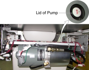
- Pour approximately 100cc of the oil into the pump.
- Power up the Table from the Gantry Service Switch.
- Raise the Table as high as possible.
- Turn off the Table from the Gantry Service Switch.
- Repeat Step 32.a through Step 32.e until Table height reaches mechanical Up-limit.
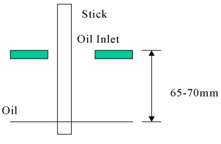
- Check the level of the oil by using a stick such as tie-wrap,
specification is shown in illustration below.
Figure 23. Check Oil Level
- Pry a lid up using a flat-head screw driver.
 |
Finalization
- Secure any loose hoses with tie-wraps.
- Raise and lower the Table repeatedly to verify that the hoses do not catch or pull excessively.
- Turn off all 3 switches (Axial Drive, HVDC, 120VAC), and re-install the Table covers.