- Topic ID: id_16157833
- Version: 2.0
- Date: Apr 9, 2020 8:47:18 PM
Home Flag and Sensor Board Assembly Replacement
Prerequisites
Overview
Procedure
- Move table to its lowest elevation.
- Remove gantry covers as required.
Refer to Parts Replacement → Gantry → Enclosure → (Cover Removal Procedure).
- notice
- Turn OFF all three (3) service switches (Axial Drive, HVDC, 120VAC).
-
- Locate the home flag by rotating gantry. Replace if any damage is visible.
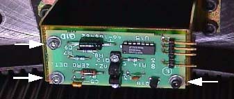
- Locate the Home Flag Sensor assembly. (See Figure 1.)
- Disconnect the harness.
- Remove the M6 screws attaching the bracket to the frame.
Figure 1. Home Flag Sensor Assembly
- Replace Sensor Assembly and Home Flag as necessary.
- Slowly rotate gantry by hand and adjust flag position to pass through the center of the opto-sensor on the sensor board. Make sure the flag is parallel to the opto-sensor.
- Perform “Resetting the C-Pulse” (located in folder).
- Reassemble gantry.
 |
Finalization
- Perform Axial Home Flag Check, located in Axial Motion Checks.
- Perform System Scanning Test (located in folder).