- Topic ID: id_16158027
- Version: 1.0
- Date: Jul 7, 2018 4:40:06 PM
HV Tank Feedback Resistor Verification
Prerequisites
Overview
This procedure verifies the kV accuracy, by actually taking scans with connecting a high voltage bleeder.
Procedure
 caution
- Perform warm-up scans, if the x-ray tube is cold.
- Remove gantry right side cover.
- Turn off all three service switches on the Service Switch Panel (Axial Drive, HVDC, 120VAC)
- Remove and set aside the top and front gantry covers.
- Rotate the gantry such that the x-ray tube is in the 3 O'clock position.
- Lock the gantry in position, using the rotational lock. Ensure that gantry rotation is locked by attempting to rotate the gantry by hand.
- Free the HV cables.
- Carefully cut ty-raps securing HV cables. Note HV cable routing.
- Loosen the cable's locking rings with a spanner wrench.
- Pull cable terminal sticks out of their receptacles on HV tanks. Oil will leak-cover them quickly!
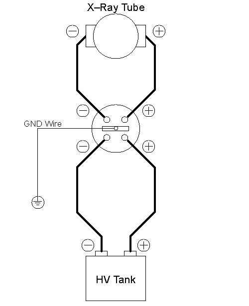
- Install the HV bleeder between the HV tank and tube. Use the
patient table to place the bleeder.
Figure 1. Bleeder Connection Block Diagram
- notice
- Unlock the gantry, and rotate the gantry such that the x-ray tube is in the 12 O'clock position.
- Lock the gantry in position.
- Setup the oscilloscope.
- To minimize noise and obtain a common ground, you should plug the oscilloscope into either the gantry or the console.
- Connect channel one probe to KV_N (TP18) and scope ground to KV_GND (TP17) on the CT Interface board in the power unit.
- If 10x probes are used, set horizontal scale = 200 ms, vertical scale = 10V/div
- Trigger channel one, negative slope, DC couple, trigger mode normal.
- Turn ON the 120VAC and HVDC ENABLE on the Service Switch Panel.
- Clear the E-Stop condition by pressing the DRIVES RESET button on the Service Switch Panel.
- Wait about 2 minutes for the gantry display to reset. No flashing lights on the gantry display should indicate this.
- On the Service Desktop, select DIAGNOSTICS, then X-RAY GENERATION, then KV & MA (X-RAY).
- Verify the following scan parameters:
-
X-Ray test type = manual
-
Gantry = Disabled
-
Exposure time = 1s
-
No of scans = 1
-
Focal Spot = Large
-
V = 80kV
-
mA = 50mA
-
- Press RUN and take scan.
- Measure the output. (It may be noisy ~2v peak-to-peak. This
is normal.)
- Using cursors on the oscilloscope, measure the mean for channel 1 from just inside the front edge to just inside the back edge of the waveform.
- Repeat for channel 2 mean.
- Repeat the measurements for 100, 120, and 140kV scans.
- Verify internal scan timer.
- Change trigger slope on oscilloscope to positive. Adjust trigger level to TTL if necessary.
- Take the following scan.
-
X-Ray test type = manual
-
Gantry = Disabled
-
Exposure time = 1s
-
No of scans = 1
-
Focal Spot = Large
-
kV = 100kV
-
mA = 50mA
-
- Measure the output.
Using cursors on the oscilloscope, measure the scan time (Δt) from just inside the front edge to just inside the back edge of the waveform.
- notice
- Reconnect HV cables from tube to tanks.
 |
 |
|
Finalization
- The scale factor for your kV measurements (at the test points) is x 20 (i.e. 4V => 8kV).
- The kV measured at the bleeder and at the test points should be within ±3% of the requested kV, respectively.
- The internal scan timer measurement should be within ±4%.
- Record the results on the HHS data sheet and / or take appropriate service action.