- Topic ID: id_16157685
- Version: 1.0
- Date: Jul 7, 2018 4:39:24 PM
Gantry Stationary Power Supply 120VAC Cable Replacement
Prerequisites
Overview
This procedure defines the steps to replace the 120VAC input power cable for stationary power supply on Optima CT540 gantry.
Procedure
 warning
- Remove gantry right side cover.note:
Replacement should be done from the front or back of the gantry.
- Refer to Parts Replacement → Gantry → Enclosure → (Cover Removal Procedure).
- If Tube is Liquid Bearing, please stop the rotor of X-ray tube in case of Liquid Bearing Tube before HVDC off. Refer to Liquid Bearing Tube Rotor stop procedure for details
- notice
- Turn OFF the three (3) main power switches (HVDC, 120VAC, and Axial Drive) on the Service Switch Panel (SSP).
- Perform all required LOTO procedures before beginning this procedure.
- Remove the gantry left side cover, top covers and front cover.
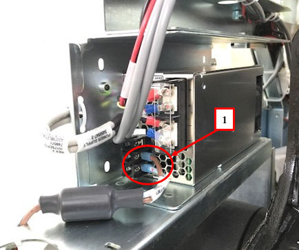
- Remove the PS AC power connections from the stationary power
supply.
Figure 1. AC Power Connection
- Cut four cable-ties (Position 1, 2 and 3).
Figure 2. PS AC Cable Disconnection
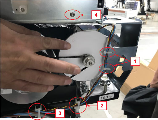 note:
note:The Tilt POT cable (RED/YEL/BLK) and the PS 120VAC power cable (BLU/BRN) are tied together.
- Disconnect PS 120VAC power cable connector and remove it.
- Remove the cable-tie base from Position 2 and install it to Position 4, reuse Position 4 screw to fix this cable-tie base. (See Figure 2)
- Install the new PS 120VAC cable and connect it to Power Supply and connector (Position 4). (See Figure 3)
- Route the PS 120VAC cable and the Tilt POT cable as shown in
below figure and fix them (Position 1, 2 and 3) by cable-ties.
Figure 3. 120VAC Cable Routing
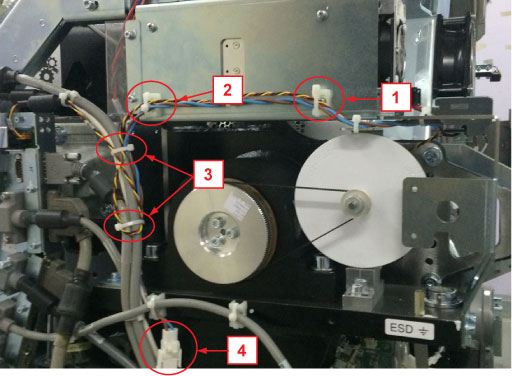 note:
note:If the cable-tie base is not on Position 2 in Site, please ignore it.
note:The Tilt POT cable (RED/YEL/BLK) is part of the Tilt POT (5380575–2), please DO NOT damage it during routing and fixing.
 |
Finalization
- Install the gantry front cover and check the front cover bracket does not interfere with the PS 120VAC power cable.
- Install the gantry top covers
- Turn on the 120 VAC, HVDC and Axial Drive service switches from
the service switch panel.
Confirm the gantry starts up normally
- Tilt the gantry all the range and check the front cover bracket does not interfere with the120VAC cable during the movement.
- Install the both side covers.