- Topic ID: id_15460146
- Version: 3.0
- Date: Apr 22, 2019 12:56:38 AM
Gantry Side Covers Removal and Re-Install
Prerequisites
Overview
This procedure explains how to remove and re-install the CT Gantry side covers.
1 Side Cover Removal
Procedure
- If removing side cover in preparation for front cover removal, move the table to its lowest position before powering off gantry.
 danger
- caution
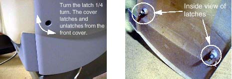
- Use an 8mm Hex wrench to unlatch the side cover from the front
cover. See Figure 1.
Figure 1. Side Cover Latches
- Remove the right side cover by lifting it upward to release
the two (2) latches, located on the top edge of the cover. See Figure 2. Once removed, the service switches should be exposed.
Figure 2. Side and Top Cover Clasp
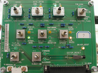
- Turn OFF the three (3) main power switches (HVDC, 120VAC, and
Axial Drive) on the Service Switch Panel (SSP) as applicable for the
service being performed . See Figure 3.
Figure 3. Service Switch Panel
- Repeat Steps 1and 2 for the left side cover.
2 Side Cover Installation
Procedure
- If installing the right side cover, remember to turn on the
3 service switches prior to cover installation.note:
If the front or rear covers were also reinstalled, after power is restored, Observe Gantry Display and Gantry Control panels during power on. Verify Power On Self Test (POST) completes normally and all cover indicators were illuminated during the POST. Verify that all Gantry control panels are functional with no ERR indicators. Also verify that the Gantry to Operator intercom is functional.
- To install a side cover, place it over the top cover and let the two (2) side cover latches slide behind the metal tabs, located on the top cover. See Figure 2.
- Use 8mm Hex wrench to secure the side cover to front cover by turning the bolts a quarter turn. See Figure 1.
3 Finalization
Procedure
- Verify all covers, especially side covers are properly secured.
- Ensure there is no interference during all tilt range.