- Topic ID: id_16157501
- Version: 2.0
- Date: Dec 21, 2018 2:36:47 AM
Gantry Cooling Fan Replacement
Prerequisites
Overview
This document defines the fan replacement process for two types of top covers, one with fixed main fans and one with the main fans removable as a pair.
The top cover fans are controlled by the stationary CFC board. You can swap the fan connections to verify that the fan is defective.
1 Cover Removal
There are two styles of top covers, one that has an independently removable section for the two main fans (2 piece top cover) and one that has all 3 fans mounted on a one piece top cover. Use the appropriate section below for your top cover style.
Procedure
 warning
- Remove gantry right side cover.
Refer to
- Stop the rotor of X-ray tube in case of Liquid Bearing Tube before HVDC off. Refer to Liquid Bearing Tube Rotor stop procedure for details.
- Turn OFF the three (3) main power switches (Axial Drive, HVDC and 120VAC) on the Service Switch Panel.
- Remove the applicable top cover and slide the rear cover backward.
 |
2 Top Fan Assembly Replacement
Procedure
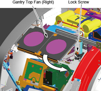
- Loosen the lock screw of the top fan assembly, and rotate the
top fan assembly.
Figure 1. Lock Screw of the Top Fan Assembly
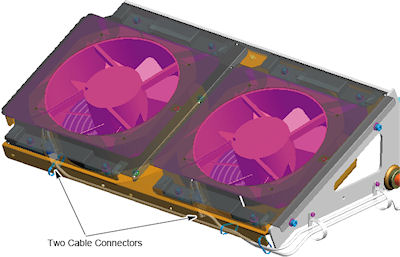
- Disconnect the cable connector from the top fan assembly.
Figure 2. Cable Connectors of Top Fan
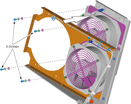
- Remove 4 screws that holding the fan to the top fan frame, and
remove the fan assembly.
Figure 3. Top Fan Removal
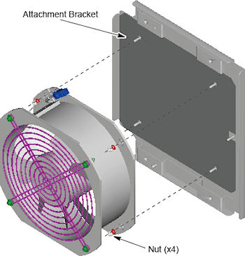
- Remove the 4 nuts, and remove the fan assembly from the attachment
bracket.
Figure 4. Fan Assembly and Attachment Bracket
- Attach the new fan assembly to the attachment bracket, and tighten the 4 nuts.
- Install the fan assembly with attachment bracket to the top fan frame using the 4 screws.
- Connect the cable connector to the fan assembly.
- Rotate the top fan assembly to the original position, and tighten the lock screw.
3 Finalization
Procedure
- Reinstall top and side covers per cover procedures including
gantry power up steps.
Refer to
- Verify all fans start immediately after a power reset to the gantry. The fans will then either turn off or change to a system defined speed dependent on the current gantry temperature.