- Topic ID: id_16157569
- Version: 2.0
- Date: Nov 7, 2019 8:55:26 PM
GDAS Astec Analog PS Replacement
Prerequisites
Overview
The ASTEC power supply is mounted on the rotating gantry. Looking through the gantry from the table end, the DAS analog power supply is serviced from the left side of the gantry.
All left/right orientation in this procedure is based on the viewpoint of an individual looking through the gantry opening from the table end.
1 Prepare the Table and Gantry
Procedure
- Position the table so it is out of the way.
- Remove gantry side covers.
Refer to .
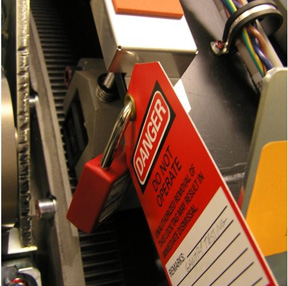
 danger
- From the right side of the gantry, turn off the Axial Drive, HVDC, and 120VAC Switches.
- Remove the top covers.
- Unplug the top cover fans.
- Remove both top covers.
- Rotate the gantry to access the Astec analog power supply from the left side (same side as TGP).
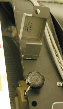
- Use the Index Lock to lock the gantry.
2 Remove the Astec Power Supply
Procedure
- If necessary, loosen the reusable Cable Clamps where found.
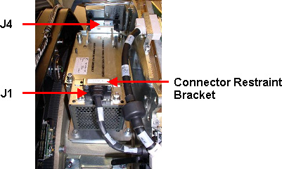
- Remove the connector restraint bracket over the J1 Connector.
- Disconnect cables to J1 and J4.
See Figure 3.
Figure 3. Connector Removal
- caution
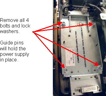
- Remove the four (4) bolts and lock washers as shown in Figure 4.
Figure 4. Remove 4 Bolts and Lockwashers
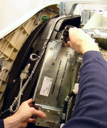
- Remove the power supply assembly from the gantry.
See Figure 5.
Figure 5. Astec GE Analog Power Supply Removal
3 Install the Replacement Power Supply
Procedure
- Insert the new power supply. Take advantage of the guide
pins on the rotating base to hold the new power supply in position.note:
Do not use Loctite compound on these bolts.
- Use the new bolts and lock washers provided. Tighten all four
(4) bolts to the specified torque setting shown in Table 6.note:
The connector thumbscrews of the ASTEC Analog power supply and backplane connector harnesses WILL BREAK very easily if using a large diameter handle screwdriver. A gentle hand torque using a small diameter handle screwdriver is recommended.
- Reconnect J1 and J5.
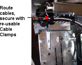
- Reroute any cables back through the removable cable clamps and
tighten them.
Figure 6. Reroute Cables and Tighten Reusable Cable Clamps
4 Finalization
Procedure
- notice
- Remove the Index Lock and all safety equipment.
- MANUALLY rotate the gantry several times while inspecting the power supply to make sure that all cables and other hardware removed are properly secured to the rotating side of the gantry, and are not interfering with rotation.
- From the right side of the gantry, turn ON the Axial Drive, HVDC, and 120VAC switches.
- Replace the top covers and connect the top cover fans.
- warning
- Adjust 5V supply's output. Refer to GDAS Power Supply Adjustment procedure.
- Replace the side covers.note:
Rebalancing the gantry is not required.
- Perform a basic scan to ensure the system is functioning normally.
 |