- Topic ID: id_16157877
- Version: 3.0
- Date: Apr 22, 2019 12:55:52 AM
Elevation Characterization Procedures (GT1700V)
Prerequisites
Overview
This procedure is for the GT1700V Table.
note:
Before and after characterization, the elevation will drive between the upper and lower hard stops from the service switches.
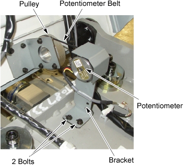
1 Height Potentiometer Adjustment
When the Height Potentiometer (elevation potentiometer) is replaced or it must be adjusted again, perform this procedure.
Procedure
- Using the Service Switches, move the table to the mechanical UP-limit position.
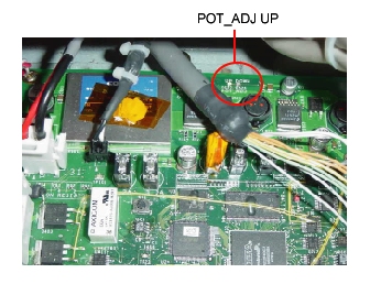
- Confirm that the “POT_ADJ UP” LED (Green) is ON.
If it is NOT ON, adjust the height potentiometer.
- Remove the Left Side cover, Left IMS Side Cover, 2 left Side Plates, and Front Base Cover.
- Loosen the two POT bracket bolts to release belt tension.
- Rotate the gear of the height POT until “POT_ADJ UP” LED is ON.
- While applying proper tension to the POT belt, secure the two POT bracket bolts.
- Confirm that the “POT_ADJ UP” LED is ON.
Figure 1. Height POT Adjustment
- Using the Service Switches, move the table to the mechanical DOWN-limit position.
- Confirm that the “POT_ADJ DOWN” LED (Yellow) is ON. If it is NOT ON, adjust the height potentiometer again.
2 Elevation Characterization
Procedure
- Move Cradle to OUT-limit position.
- Remove the Top Side Cover (Right), Right Side Base Cover, and Front Base Cover.
- Set the service switch (MODE_SEL) to the SERVICE to enter the
service mode. See Figure 2.
Figure 2. LED's on GTCB board
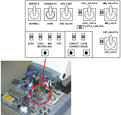
- Confirm that the “ELEV” LED on the GTCB board in the table is ON. If it is NOT ON, press the “Motion Target” button until “ELEV” LED is ON. See Figure 2.
- notice
- Press and hold the service switch (ACTION) to the IN/UP position
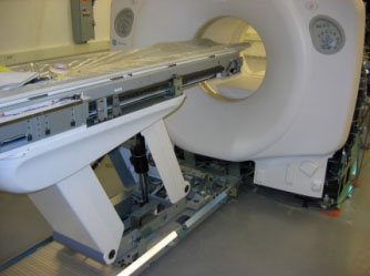
to move the Table to the mechanical UP-limit position. See Figure 3.
Figure 3. Table at Up-limit Position (Higher Than Scannable Range)
- Confirm that the “POT_ADJ UP” LED (Green) is ON.
If it is NOT ON, perform Height Potentiometer Adjustment. Refer to Height Potentiometer Adjustment.
Figure 4. “POT_ADJ UP” LED (Green)
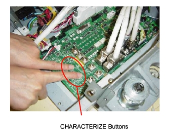
- Press the two Characterize buttons at
the same time to start characterization. See Figure 5.
Figure 5. Starting Characterization
- Confirm that the “UP/IN” LED is ON. See Figure 2.
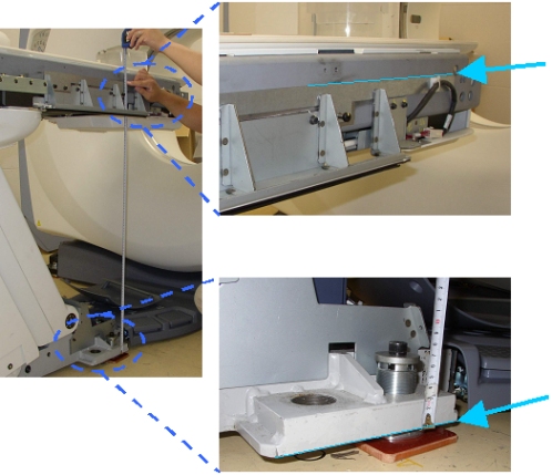
- Using the Service Switches, move the table at 980 +/- 0.5mm
of the distance between characterization points. The distance measured
is between the bottom of the Table base (not floor) and the top of
the characterization plate. See Figure 6.
Figure 6. Elevation Characterization Points
- Press the two Characterize buttons at the same time. See Figure 5.
- Confirm that the “DOWN/OUT” LED is ON. See Figure 2.
- Using the Service Switches, move the table at 700 +/- 0.5mm of the distance between characterization points. The distance measured is between the bottom of the Table base (not floor) and the top of the characterization plate. See Figure 6.
- Press the two Characterize buttons at the same time. See Figure 5.
- Confirm that both the “UP/IN” LED and “DOWN/OUT” LED are ON. See Figure 2.
- Using the Service Switch, move the Table to the mechanical down-limit position.
- Press the two Characterize buttons at the same time. See Figure 5.
- After 10 seconds (to write characterization data to the flash memory), confirm that both LED's (UP/IN and DOWN/OUT) are OFF. See Figure 2.
- If both LED's blink during the procedure, it means that characterization failed. Retry characterization.
- Using the Service Switches, move the table to a position in which the distance between the characterization points is: 800 +/- 1.0mm. The distance measured is between the bottom of the Table Base and the top of the characterization plate. See Figure 6.
- Set the service switch (MODE_SEL) to the NORMAL position for customer use. See Figure 2.
 |
3 Finalization
Procedure
- Confirm that service switch (MODE_SEL) is set to NORMAL position and install the covers in the reverse order of removal.