- Topic ID: id_16157910
- Version: 2.0
- Date: Apr 9, 2020 8:49:22 PM
Detector Memory Board Replacement
Prerequisites
Overview
Replace failed Detector Memory Board (DMB):
-
Remove covers.
-
Remove tie-wraps.
-
Replace part.
-
Assemble gantry
-
Verify operation
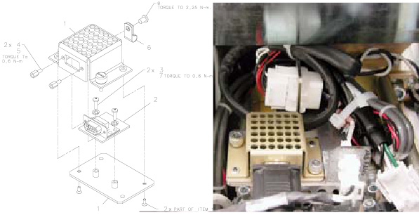
Figure 1. Detector Memory Board Replacement
Procedure
- Position the table to its lowest position.
- Remove gantry right side cover.
- notice
- Turn OFF Axial Enable, HVDC, and 120VAC switches on the Service Switch panel.
- Cut Tie-wraps as needed.
- Disconnect cable connection from DMB assembly.
- Loosen thumbscrews with the flat-blade screwdriver and remove assembly from mounting bracket.
- notice
- Remove the HD Connector Screw locks with the 3/16” nut-driver.
- Remove two (2) 2.5 mm hex screws from the under side of the assembly.
- Remove the two (2) Phillips screws holding the module to the base.
- Install new module in reverse order.
 |
|
Finalization
- Restore power and verify the error log is clear of faults.