- Topic ID: id_16157860
- Version: 4.0
- Date: Jan 20, 2020 8:36:23 PM
Cradle Lock Assy Replacement
Prerequisites
Overview
Procedure
- Raise the Table to maximum height.
- Move the Cradle and IMS to OUT limit position.
(For Global PET/CT Table, with fixed position IMS) Move the Cradle to OUT limit position.
(For Global PET/CT Table) Move the Cradle and IMS to OUT limit position.
(For GT1700 and GT2000 Table) Move the Cradle and IMS to OUT limit position.
(For GT1700V Table) Move the Cradle to OUT limit position.
- Remove power from Table by turning off 120VAC, Axial Drive and HVDC switches on Service Switch Panel.
- Remove the following Table covers:
-
Top Cover (Right/Left)
-
Rear Top Cover
-
Rail Cover (Right)
-
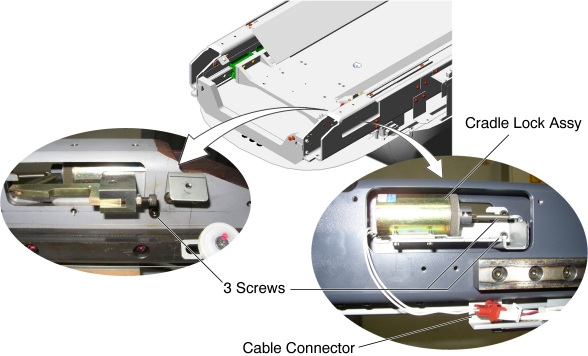
- Disconnect the Lock Assembly cable connector.
- Unscrew 3 screws, and remove the Lock Assembly from the Table.
Figure 1. Cradle Lock Assy Removal
- Install the new Lock Assembly into place, and tighten the 3 screws.
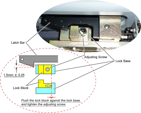
- Verify that the gap between the lock base/block and the cradle
lock is 1.5mm ± 0.25.
If not, adjust the lock block position using adjusting screw.
Figure 2. Cradle Lock Adjustment
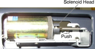
- Push the solenoid head to release the cradle lock and move the
cradle IN and OUT several times, and verify that the cradle lock is
unlocked.
Figure 3. Solenoid Head of Cradle Lock Assembly
- Release the solenoid head, and verify that the cradle locking function works well.
- Connect the Lock Assembly cable connector.
Finalization
- Re-install the Table covers.
- Power up the Table from the Service Switch Panel.
- Verify that the cradle IN/OUT function is operating normally.