- Topic ID: id_16158017
- Version: 4.0
- Date: Jan 20, 2020 8:35:25 PM
Cradle Encoder Spool Wire Replacement
Prerequisites
Overview
Procedure
- Raise the Table to maximum height.
- Perform this step if applicable:
(For Global PET/CT Table, with fixed position IMS) Move the Cradle to OUT limit position.
(For Globla PET/CT Table) Move the Cradle and IMS to OUT limit position.
(For GT1700 and GT2000 Table) Move the Cradle and IMS to OUT limit position.
(For GT1700V Table) Move the Cradle to OUT limit position.
- Remove power from Table by turning off 120VAC, Axial Drive and HVDC switches on Service Switch Panel.
- Remove the following Table components and covers:
-
Cradle
-
Top Cover (Right/Left)
-
Rear Top Cover
-
Rail Cover (Right/Left)
-
Top Plate (Front/Middle/Rear)
-
Front Top Cover
-
Tray-F
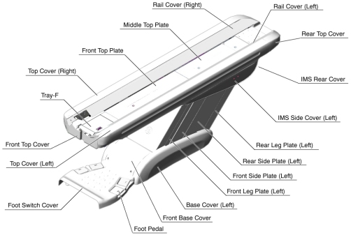
Figure 1. Table Covers
-
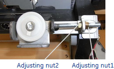
- Loosen the adjusting nut-1, to remove tension from the cradle
wire.
Figure 2. Adjusting Nut
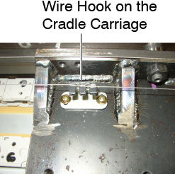
- Remove the cradle wire from the wire hook on the cradle carriage.
Figure 3. Wire Hook
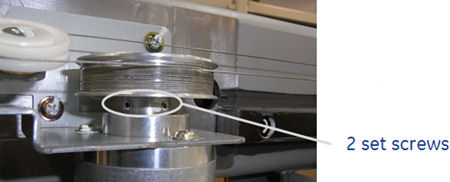
- Loosen 2 set screws on the wire drum, and remove the wire drum
from the cradle encoder, then remove the cradle wire assembly from
the Table.
Figure 4. Set Screws of the Wire Drum
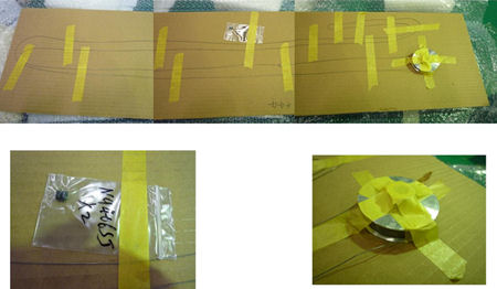
- Install the new cradle wire assembly:
Figure 5. FRU Unit of the Cradle Wire Assembly
- Move the cradle carriage to IN limit position until the carriage hits against the front stopper of the table.
- Attach the wire drum to the cradle encoder, and tighten the 2 set screws (torque: 1.67 N-m), to fasten the wire drum.
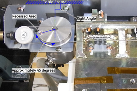
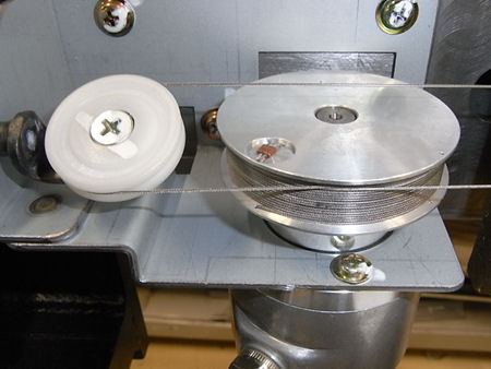
- Position the recessed area of the wire drum as shown in Figure 6 below, and fix
the drum with the adhesive tape (or an equivalent) to prevent the
rotating of the drum.
Figure 6. Wire Drum Positioning
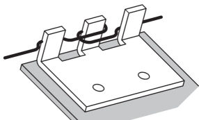
- Set the cradle wire to the wire hook as shown in illustration
below.
Figure 7. Wire Hook on the Cradle Carriage
- Route the cradle wire as shown in Figure 8 and Figure 9.
Figure 8. Cradle Wire Routing (Rear)
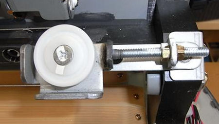
Figure 9. Cradle Wire Routing (Front)
- Take off the adhesive tape from the wire drum.
- Rotate the adjusting nut1 in the CW direction until the distance
D is 2 ± 0.5 mm.
Figure 10. Adjusting Nut 1
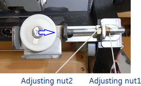
Figure 11. Wire Tension
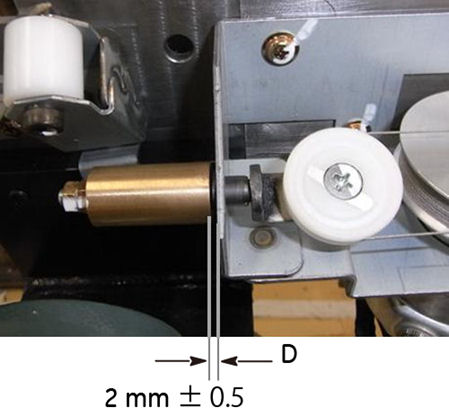
- Move the cradle carriage In/Out limit position, and verify that the wire is properly wound onto the wire drum and the carriage moves smoothly.
- Move the cradle carriage In and Out completely 5 cycles to ensure that the distance D is 2 ± 0.5 mm (see Figure 11).
- Tighten the adjusting nut2 to fix the position of the pulley (see Figure 10).
Finalization
- Power up the Table from the Service Switch Panel.
- Perform Cradle Characterization.
- Turn off all 3 switches (Axial Drive, HVDC, 120VAC), and re-install the Table covers.