- Topic ID: BJ_220224_B01
- Version: 2.0
- Date: Mar 2, 2022 10:23:13 PM
Cradle Drive Roller Assy Replacement
Prerequisites
Overview
This procedure defines the replacement process for the cradle drive roller replacement, please order the assembly part 5722929 to replace the defective drive roller.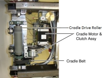
Figure 1. Cradle Drive Roller
Procedure
- Raise the Table to maximum height.
- Move the Cradle/IMS to OUT limit position.
- Remove power from Table by turning off 120VAC, Axial Drive and HVDC switches on Service Switch Panel.
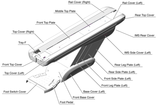
- Remove the following Table component and covers:
-
Cradle
-
Top Cover (Right/Left)
-
Tray-F
-
Front Top Cover
-
Rail Covers (Right/Left)
Figure 2. Table Covers
-
- Remove the Cradle Motor and Clutch Assy according to Cradle Motor and Clutch Assy Replacement.
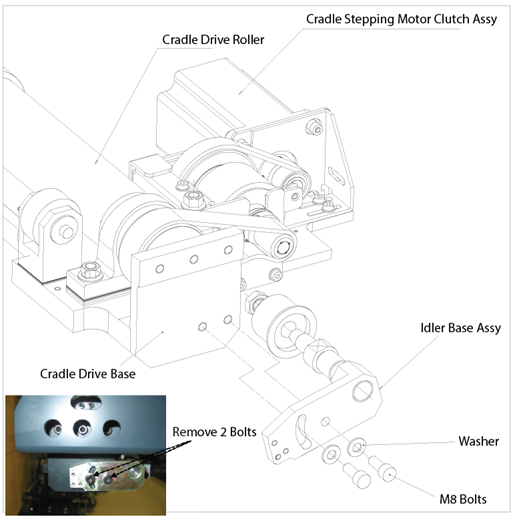
- Remove two (2) M8x20mm bolts and washers to release the Idler Base Assy from the Cradle Drive Base.
Figure 3. Release Idler Base Assy
- Loosen six (6) M8x20mm bolts to remove the Cradle Drive Roller Assy from the Right/Left Frame Pipe.
Figure 4. Cradle Drive Roller Assy Removal
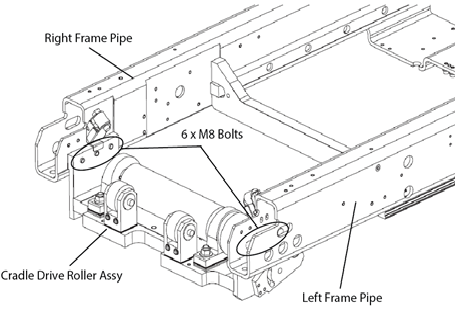
- Install the new Cradle Drive Roller Assy in place, and tighten six (6) M8 bolts, apply torque to 27.9Nm. Figure 4
- Reinstall the Idler Base Assy to the Cradle Drive Base by using two (2) M8 bolts and washers, apply torque to 27.9Nm. Figure 3
- Restore the Cradle Motor and Clutch Assy according to Cradle Motor and Clutch Assy Replacement.
Finalization
- Re-install the Cradle and Table covers.
- Power up the Table from the Service Switch Panel.
- Move the cradle In/Out completely 10 cycles, and verify that the cradle movement is operating normally.