- Topic ID: id_11038783
- Version: 3.0
- Date: Apr 22, 2019 12:56:19 AM
AC Box Assembly Replacement (5412524–2)
Prerequisites
Overview
1 Removal Procedure
Procedure
- Select one of the following methods to Power OFF the Operator
Console:
- If Applications are up, click on the Shut Down button and select Shutdown.
The Operator Console monitor will display a 'Power Down' message when it is acceptable to power OFF the Operator Console.
- If Applications are down, open a Unix Shell. Type: halt.
- If Applications are up, click on the Shut Down button and select Shutdown.
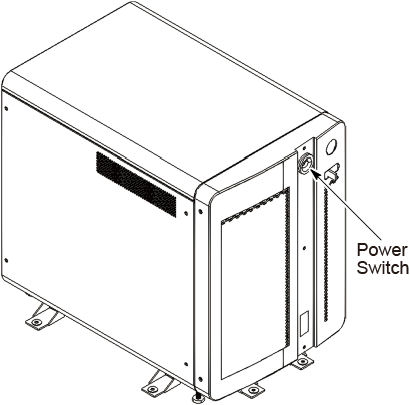
- Power OFF the console at the front panel switch.
Figure 1. Power Switch
- Remove the side and top covers.
Refer to
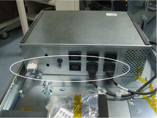
- Disconnect all cable connectors from the AC box assembly.
Figure 2. Cable Connectors of AC Box Assembly
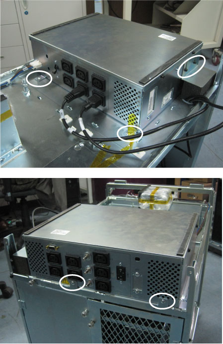
- Remove six screws from AC Box as below illustration.
Figure 3. AC Box Assembly Removal
- Cut the tie-wraps holding the AC box power cable to the OC chassis.
Figure 4. Cut Tie-Wraps

- Unscrew three screws to remove the flanged inlet from the OC
chassis.
Figure 5. Remove Flanged Inlet
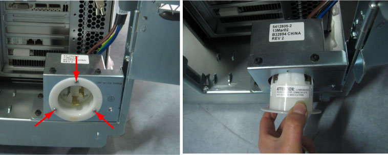
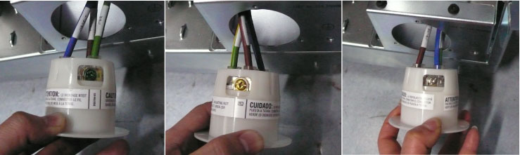
- Mark and remove the wires of AC box power cable from the flanged
inlet by unscrewing their three screws.
-
Green screw: J19-E (Green)
-
Yellow screw: J19-LINE (Brown)
-
White screw: J19-NEUT (Blue)
-
- Remove the AC box assembly with power cable from the OC chassis.
2 Installation Procedure
Procedure
- Position the new AC box assembly on the OC chassis and screw its six screws.
- Route the AC box power cable, and reconnect the wires of AC box power cable to the flanged inlet by screwing its three screws.
- Fix the flanged inlet to the OC chassis by screwing its three screws.
- Re-tie the AC box power cable with tie-wraps shown in Figure 4.
- Re-Connect all cable connectors to the AC box assembly.