- Topic ID: id_11038760
- Version: 3.0
- Date: Mar 5, 2020 12:15:08 PM
Slipring Brush Disconnects Troubleshooting
This document pertains to the following systems:
-
LightSpeed Series
-
BrightSpeed / BrightSpeed Select
-
Optima CT520 / CT540
-
Discovery CT590 RT / Optima CT580 / Discovery RT
-
Brivo CT385
1 Check Disconnects
- On the CSD, select Diagnostics > RTS Viewer. See Figure 1.
note:
For non-VCT systems, use getStats or On the CSD, select Error Logs > System Browser > RunTime Statistics.
Figure 1. ORP Low Speed Report
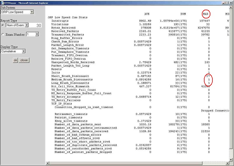
- From the dropdown list in the SubSystem field select ORP Low Speed.
- From the dropdown list in the Report Type field select Num of Exams.
- In the field to the right of Report Type enter 30.
- From the drop-down list in the Display Type field select Cumulative. A report appears similar to that in Illustration 1.
- Ensure that the value in the MAX column is <=1 disconnect per exam for short, medium, and long disconnects.
- If the MAX value is >1, perform the service procedures in Section
4.2 - Section 4.5 of this document.
Corrective Action Summary
- On the CSD, select Diagnostics > RTS Viewer. See Figure 2.
note:
For non-VCT systems, use getStats or On the CSD, select Error Logs > System Browser > RunTime Statistics.
Figure 2. TGP Low Speed Report
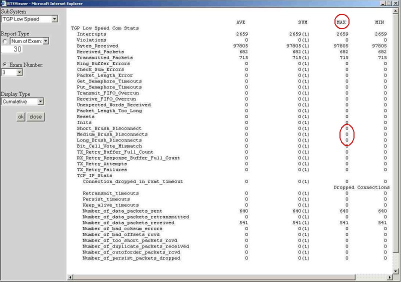
- From the dropdown list in the SubSystem field select TGP Low Speed.
- From the dropdown list in the Report Type field select Num of Exams.
- In the field to the right of Report Type enter 30.
- From the dropdown list in the Display Type field select Cumulative. A report appears similar to that in Illustration 2.
- Ensure that the value in the MAX column is <= 1 disconnect per exam for short, medium, and long disconnects.
- If the MAX value is >1, perform the service procedures in Section 4.2 - Section 4.5 of this document.
Corrective Action Summary
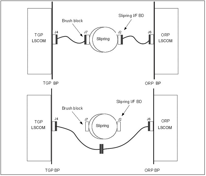
Optional procedure: Perform the Slipring Bypass Procedure described in Figure 3 to perform a stationary test for disconnect failures.
Figure 3. Bypass Procedure
2 Remove Brush Block
- Move table to its lowest elevation.
- Remove the gantry right side cover.

- notice
- Turn OFF all three service switches (Axial Drive, HVDC, 120 VAC) on the Service Switch Panel.

 danger
- Perform a LOTO for system power (A1 disconnect) prior to replacing this component.
- Remove gantry covers as required. Refer to the Service Methods manual: Parts Replacement > Gantry > Enclosure > (Cover Removal Procedure).
- Remove the slipring safety covers.
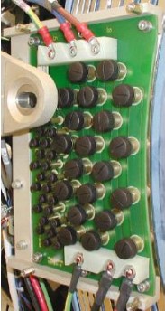
- Disconnect all connections to the brush block (Figure 4)
Figure 4. Slipring Brush Block Assembly
- Remove the four 6 mm cap screws that secure the brush block assembly to the gantry.
- Carefully remove the brush block.
3 Cleaning the Slipring
Follow this procedure to properly perform a slipring cleaning.
|
|
- Clean off the dust from the slipring tracks and carefully around the block with a HEPA vacuum cleaner and the soft brush attachment.
- notice
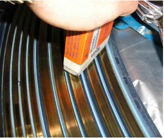
- With the slipring eraser (Figure 5), carefully rub the tracks, using a large, sweeping motion.
Figure 5. Slipring Eraser
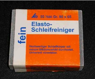
IMPORTANT: Do not rub intensely in one spot for a long period of time.
The ring color should return to a shiny brass color (Figure 6).
Figure 6. Cleaning With The Eraser
- Clean the track again with the HEPA vacuum cleaner and the soft brush attachment.
- Wipe the track with a soft white linen cloth, while using the vacuum cleaner to remove any other debris.
- Remove gloves and wash hands thoroughly after cleaning the slipring.
4 Replacing the Signal Brushes
|
|
- Remove all individual signal brushes from the block by unscrewing the brush cap and extracting the brushes.note:
Brushes are spring loaded to ensure constant contact with the slipring during operation. When the block is removed, the springs relax, causing the brushes to bound outwards.
- Install new signal brushes on the block.
IMPORTANT: Brush tip damage is possible. Brush tips are extremely brittle. Do not apply sideways force, because they will break. Any brush that has been damaged in this fashion must be replaced.
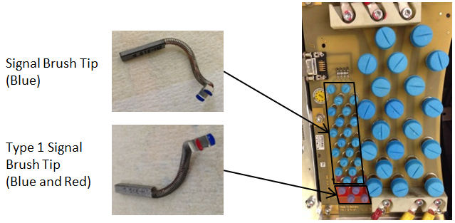
IMPORTANT: There is a second supplier for Brush tips (marked blue) which can be mixed with the current brush tips, except for the following condition on Signal Brushes:
If any Signal brush marked Blue (will have “H” etched on the brush) is used, Type 1 (High Silver Content) Signal Brushes marked with Blue and Red together on Spring End must be used instead of brushes marked Red”.
note:Type 1 Signal Brush Tip FRU kit (5350798–2) consists of four brush tips (marked Blue and Red together). It is recommended to replace all four signal lines with Type 1 brush tips (marked Red) at a time for future replacement with HELWIG’s blue signal brush tip.
Figure 7. Current Brush Block (CARBEX)
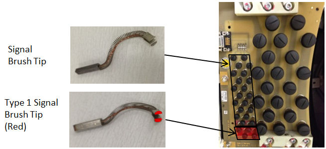
Figure 8. Second Supplier’s Brush Block (HELWIG)
5 Aligning the Brush Block
- Carefully install the brush block by exerting even pressure perpendicular to the ring surface.
- Secure the brush block with the four 6 mm cap screws. Do not tighten the cap screws.
- Carefully push the brush block against the position adjustment set screws in the mounting bracket.
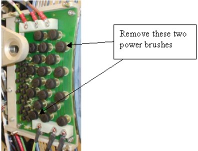
- Remove the two brushes from the inside HVDC ring top and bottom
(Figure 9). Remember their orientation for later installation.
Figure 9. Power Brushes to Use for Alignment
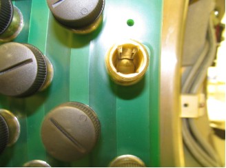
- Use a flashlight to verify that block position is adjusted so the brushes ride in the center of their tracks (Figure 10).
Figure 10. Correct Brush Block Alignment
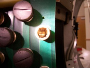
 note:Incorrect alignment occurs if either side of the track is visible (Figure 11). If necessary, adjust the brush block setscrews to center the brush. To measure radial and axial runout, see Install New Slipring procedure.
Figure 11. Incorrect Brush Block Alignment
- Torque the four 6 mm cap screws to 7.9 N-m.
- Do the following before reassembling the gantry:
- Check all power connections to the slipring – 208 V on the back side of the ring.
- Check the brush block connections, then visually inspect the harness with the Sub-D connector.
- Check the small slipring i/f board on the rotating part of the ring.
- Verify that the 9-pin connector is securely connected to the board.
- Use a 2.5 mm hex key to verify that all five 3 mm cap screws
are tight.
note:
Visually inspect all screws. In the past there have been occasions where screws were used that were too long.
- Reassemble the gantry covers.
6 Finalization
- Document the number of gantry revolutions.
- Perform a hardware reset using console gantry reset (Hardwire).
- Acquire 10 scouts (120 kV/40 mA., 1000 mm table movement).
- Acquire 100 axials (120 kV/80 mA., 0.5 sec. scan).
- Acquire 1 helical (120 kV/40 mA., 30 sec.scan).
- Acquire 10 axials (120 kV/400 mA., 4 sec.scan).
- Verify that there is no increase in LSCOM errors.