- Topic ID: BJ_210315_Y01
- Version: 2.0
- Date: Dec 22, 2021 11:18:12 PM
Stand Alone Console Theory
1 Overview
The Stand Alone Console is the master operation controller of the CT system. The computer controls the acquisition, reconstruction, image generation, display, archive, and output (i.e. film, DICOM, etc.) of patient data and images.
The Stand Alone Console accomplishes these tasks by taking input from the user via keyboard and mouse. This input along with the operating and application software loaded on the computer is used to control and communicate with the component groups responsible for image generation, reconstruction and display. The Stand Alone Console communicates via Gigabit Ethernet interface with the following:
-
Gantry/Table
-
AW Workstation (Optional)
-
Hospital Network
The Stand Alone Console uses a Commercial Off The Shelf (COTS) Workstation (HP - Z8G4). The Host Computer’s video display ports, connected to two display monitors, handle visual display of the Prescription and Display screens. Optionally, the Display monitor video signal can be shared with a second Scan Room display utilizing a video splitter/amplifier.
The User keyboard and mouse connect with the Z8G4 computer via standard USB 3.0 interfaces. The Stand Alone Console integrated audio controller is used for the Autovoice feature and interfaces with the GSCB via standard analog audio PC connections on the Stand Alone Console . The Stand Alone Console also interfaces with an external Peripheral Media Tower via USB 3.0.
2 PC Model HP Z8G4
The Host Computers have historically been Workstation computers supplied by OEM vendor Hewlett Packard. The model discussed below is the Z8G4, which is the latest in the series of HP Workstations. The following is a brief overview of the hardware and software theory associated with the Z8G4.
Obtain complete details of the HP Z8G4 PC from Hewlett Packard’s support web site: http://www.hp.com/. Click on Support & Drivers and search by PC model number.
Reference the HP Z8G4 Maintenance and Service Guide manual by clicking on the following PDF link.
HP Z8G4 Workstation Maintenance and Service Guide
Reference the HP Z8G4 Quickspec manual by clicking on the following PDF link.
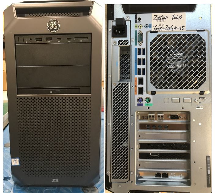
Figure 1. Stand Alone Console with HP Z8G4
2.1 Z8G4 Computer Hardware Overview
The Z8G4 computer is an Intel® Xeon™ processor-based workstation configured by GE Healthcare for use as the Standalone Console. Its basic configuration is:
2.1.1 Motherboard
The (Z8G4) computer motherboard utilizes a Dual Intel Xeon Processor 4215 Motherboard (called the “Systemboard” in HP terminology) with:
-
Dual Intel® Xeon™ 4215 2.5GHz 8 Core
-
24 Memory Slots (6TB max.)
-
Integrated with:
-
Audio
-
GBE NIC Port (eth 2 & 3)
-
USB 3.0 ports (6 rear & 4 front)
-
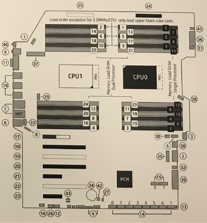
Figure 2. HP’s Z8G4 Computer Motherboard Component Layout
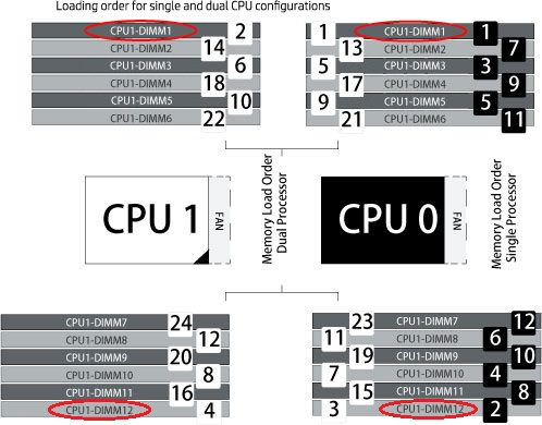
2.1.2 DIMM Memory Modules
The (Z8G4) computer is equipped to handle up to 24 memory DIMM Modules in a variety of configurations. The configuration for Systems; Tri-Channel Mode 4 Slots each containing a 16GB DDR4-2666 or higher frequency Reg ECC RDIMM Memory Module for a total of 64 GB.
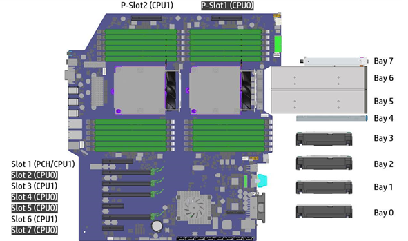
Figure 3. Z8G4 Computer Motherboard Layout - Utilization
2.1.3 Z Turbo Drive Storage Features and PCIe Solid State Drives
The HP Z8G4 Workstation can support up to 8 Z Turbo Drives. All Z Turbo Drives qualified on HP Z8G4 are NVMe storage devices. Up to four M.2 modules may be installed via two HP Z8 M.2 Adapter Modules, and up to four additional M.2 modules may be added via a Z Turbo Drive Quad Pro carrier. The use of two HP Z8 M.2 Adapter Modules requires that two CPUs are installed in the workstation.
The Personality Module carriers can accommodate two M.2 modules up to the 22110 form factor. The Z Turbo Drive Quad Pro can accommodate four modules up the 22110 form factor.
Samsung PCIe NVME M.2 solid state drives, located in HP Z turbo drives as storage disks . The System disk (P-Slot2_CPU1_0) holds the CT Operating System and Application software. The Image disk and raw date disk (P-Slot1_CPU0_0 or P-Slot1_CPU0_1) separately utilizes one of 512GB NVME SSD to hold patient image data or raw data. The Software is designed to auto identify which one is for image and for raw data when first LFC. The Z-turbo Drives are installed in the host computer motherboard PCIe P_Slot2 and P_Slot1. and M.2 NVME SSD is connected via M.2 interface in Z-turbo drives. Reference Illustration 4, PCIe Connectors.
Figure 4. HP Z8G4 Z Turbo Drive Slots
2.1.4 Dual Port GbE Ethernet Card
The Dual-Port Gigabit Ethernet HP I350 - T2 (PCIe3 x8) card, located in Slot 7 of the (Z8G4) computer motherboard, expands the Z8G4’s Ethernet interface to 4 total external ports (eth0-eth3).
2.1.5 Graphic Card
The NVidia Quadro P620 card, located in Slot 2 of the (Z8G4) computer motherboard, drives the Scan and Display monitors. This graphics card has 2GB GDDR5 memory and utilizes three mini Display Port (DP) output for the LCD monitors.
2.1.6 Recon GPU Card
The NVidia Quadro RTX5000 Graphics card, located in Slot 4 of the (Z8G4) computer motherboard, provides the reconstruction engine for the image generation subsystem. This Recon GPU card contains 16GB GDDR6 memory.
2.1.7 KDIP Card
The KDIP (PCIe x4) card, located in Slot 1 of the (Z8G4) computer motherboard, provides the interface for the incoming scan data coming from the Gantry/Detector/DAS subsystem. It converts the optical signal received from the Gantry into electrical raw data and writes that data to one of the double buffers on the card. When the received data count reaches a predetermined value, it will switch over to the other buffer. The Host Computer then receives this data via the PCI bus. This card supports 4 lanes, 2.5GT/s, PCIe bus interface in the FPGA, and should be able to support 833MB/sec data rate optical fiber interface.
2.1.8 Power Supply (PSU)
A 1125 Watt PSU powers the (Z8G4) computer. The rated voltage range is 100-240 VAC, with line frequency of 50-60 Hz, auto switching.
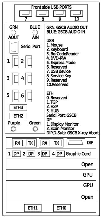
2.2 (Z8G4) Computer Connections
Refer to the following Illustration for cable interconnect information.
Figure 5. (Z8G4) Computer Connections